Introduction
ringgrid is a pure-Rust library for detecting dense ring calibration targets. It detects markers with subpixel accuracy, decodes unique IDs from the shipped baseline 893-codeword profile (with an opt-in extended profile available for larger ID spaces), estimates a board-to-image homography, and returns structured results ready for downstream camera calibration.
Since 0.8, targets are described compositionally rather than as a single fixed layout: a hex or rect lattice, coded (16-sector, ID-bearing) or plain rings, and optional origin fiducials for plain targets that carry no per-marker identity. See The Compositional Target Model for the full picture.
No OpenCV bindings — all image processing is implemented in Rust.
| Printable target | Detection overlay |
|---|---|
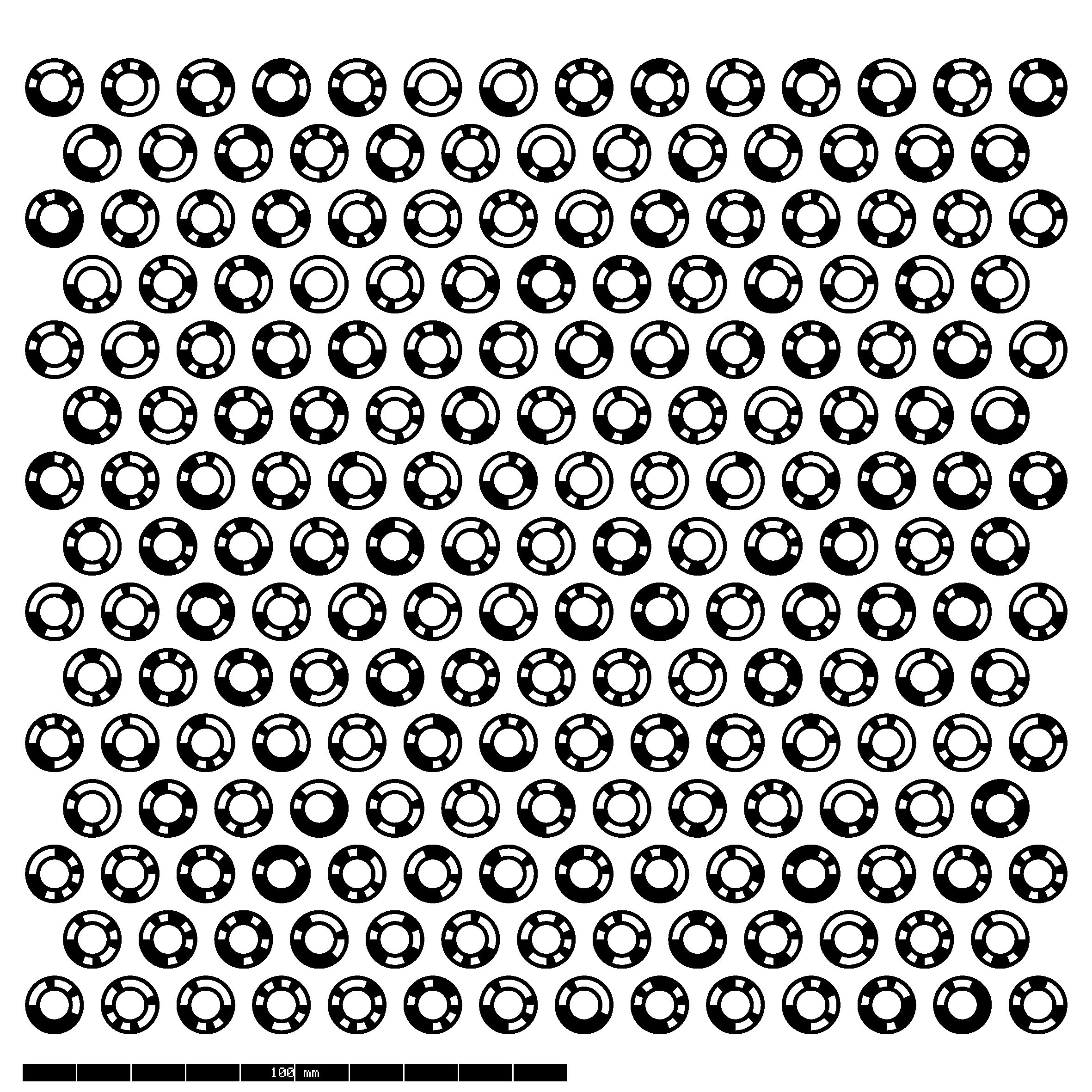 | 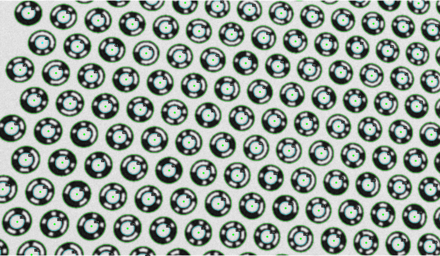 |
The Problem
Camera calibration requires detecting fiducial markers — known patterns printed on a calibration target — with high geometric precision. Traditional approaches use checkerboard corners or square markers (ArUco). These patterns have limitations:
- Checkerboards provide subpixel corner accuracy but carry no per-corner identity, making automatic correspondence ambiguous when the full board is not visible.
- Square markers (ArUco, AprilTag) encode identity in a binary grid, but their corners are detected via contour intersection, which limits subpixel precision.
ringgrid introduces a different target design: concentric ring markers with binary-coded sectors, arranged on a hex lattice.
The Solution
Each ringgrid marker consists of two concentric rings — an outer ring and an inner ring — separated by a 16-sector binary code band that encodes a unique ID. This design provides three key advantages:
-
Subpixel edge detection. Ring boundaries produce strong, omnidirectional intensity gradients. The detector samples edge points along radial rays and fits an ellipse using the Fitzgibbon direct least-squares method, achieving center localization well below one pixel.
-
Projective center correction. Under perspective projection, the center of a fitted ellipse is not the true projected center of the circle. ringgrid fits both the outer and inner ring ellipses and uses their conic pencil to recover the unbiased projected center — without requiring camera intrinsics.
-
Large identification capacity. The 16-sector binary code band ships with a stable 893-codeword baseline profile at minimum cyclic Hamming distance 2, plus an opt-in 2180-codeword extended profile when larger ID capacity matters more than the baseline ambiguity guarantee without introducing new polarity ambiguity beyond the shipped baseline.
What You Get
The detector returns a DetectionResult containing:
- A list of
DetectedMarkerstructs, each with:- Decoded ID (from the active codebook profile; baseline by default)
- Subpixel center in image coordinates
- Board coordinates in millimeters when the ID is valid for the active layout
- Fitted outer and inner ellipses
- Quality metrics (fit residuals, decode confidence) and detection source
- A board-to-image homography (when enough markers are decoded)
- Coordinate frame metadata describing the output conventions
See Detection Output Format for the exact JSON shape written
by the CLI and the corresponding Rust DetectionResult fields.
Detection Modes
ringgrid supports four high-level detection modes:
- Simple detection — single-pass detection in image coordinates. No distortion correction.
- Adaptive scale detection — multi-tier detection that auto-selects scale bands (or uses explicit tiers) for scenes with large marker size variation.
- External pixel mapper — two-pass detection using a user-provided coordinate mapping (e.g., camera distortion model). Pass-1 finds seed positions, pass-2 refines in the undistorted working frame.
- Self-undistort — automatic estimation of a single-parameter division distortion model from the detected ellipses, followed by a corrected second pass. No external calibration required.
Who This Is For
This book is for engineers integrating high-precision fiducial detection into:
- Camera calibration pipelines
- Photogrammetry and 3D reconstruction
- Computer vision applications requiring high-precision fiducial detection
- Metrology and measurement systems
ringgrid is a Rust library, but you do not have to write Rust to use it: it also ships Python, C/C++, and WebAssembly bindings and a command-line tool — see Language Bindings.
Book Structure
- Fast Start — one-command workflow to generate
target_spec.json+ printable SVG/PNG and run first detection - Targets — the compositional target model: hex/rect lattices, coded/plain marker rings, optional origin fiducials
- Marker Design — anatomy of the ring marker, coding scheme, and hex lattice layout
- Detection Pipeline — a walkthrough of every detection stage
- Mathematical Foundations — full derivations of the core algorithms (ellipse fitting, RANSAC, homography, projective center recovery, division model)
- Using ringgrid — configuration, output types, detection modes, and CLI usage
- Language Bindings — Python, C/C++, and WebAssembly/npm
Upgrading across a pre-1.0 release? Per-interface migration notes live in
docs/migrations/.
Fast Start
This section gets you from zero to:
target_spec.json(target config used by the detector)- printable
target_print.svg - printable
target_print.png - fabrication-ready
target_print.dxf
in three commands, using the published ringgrid binary.
0. Install
cargo install ringgrid --features cli
This puts a ringgrid binary on your PATH. (Library users run
cargo add ringgrid; Python users pip install ringgrid.)
1. Get a recipe
A recipe is the small TOML (or JSON) file that describes the target you want. Start from a built-in example — the classic hex coded board:
ringgrid example --name hex_coded --out hex_coded.toml
Run ringgrid example --list to see all built-in recipes (the six valid
combinations of {hex, rect} × {coded, plain} × {origin dots, no dots}).
2. Generate target JSON + SVG + PNG + DXF
ringgrid gen hex_coded.toml --out ./out/target_faststart
Other paths (the TargetLayout Rust API, custom recipes, and the plain /
rectangular target families) are covered in
Target Generation.
3. Output files
After the command finishes, you will have:
./out/target_faststart/target_spec.json./out/target_faststart/target_print.svg./out/target_faststart/target_print.png./out/target_faststart/target_print.dxf
4. Detect against this board
ringgrid detect \
  --target ./out/target_faststart/target_spec.json \
  --image path/to/photo.png \
  --out ./out/target_faststart/detect.json
detect.json contains the final marker list, coordinate-frame metadata,
optional homography/RANSAC statistics, and optional mapper diagnostics. See
Detection Output Format. Omit --out to print the JSON to
stdout instead.
Developing ringgrid. If you also need synthetic camera renders and ground truth for benchmarking, those live in the in-repo Python tooling (
tools/gen_synth.py) and require a repository checkout. See Development.
5. Scale handling
- Start with default detection first (
Detector::detect, or CLIdetect). - For scenes with very small and very large markers in the same image, use the
adaptive multi-scale APIs (exposed via the Rust and Python libraries):
Detector::detect_adaptiveDetector::detect_adaptive_with_hintDetector::detect_multiscale
Next Reads
- Full configuration and recipe reference: Target Generation
- CLI usage and detection flags: CLI Guide
- Detection JSON schema: Detection Output Format
- Adaptive scale details: Adaptive Scale Detection
Tutorial: Both Targets, End to End
This tutorial walks the full arc — generate → detect → interpret — for the two headline targets ringgrid supports:
- a coded hex target (16-sector rings, decoded to globally unique IDs), and
- a plain rect target (uncoded rings on a rectangular lattice, labeled by lattice coordinate and — with origin dots — anchored to absolute board mm).
Each generation step writes the same four artifacts: the canonical
target_spec.json, a printable .svg and .png, and a .dxf (2D CAD in
millimeters) for laser/CNC fabrication. See Target
Generation for every recipe field and the Compositional
Target Model for the geometry.
These two targets are hex_coded and rect_plain_dots — two of the six
built-in example recipes. All six combinations of {hex, rect} × {coded, plain}
× {origin dots, no dots} are available (see the
target matrix); origin-dot anchoring
now works for hex plain targets too.
Install the CLI once:
cargo install ringgrid --features cli
Part A — Coded hex target
1. Generate
Grab the built-in recipe and render it:
ringgrid example --name hex_coded --out hex_coded.toml
ringgrid gen hex_coded.toml --out ./out/hex
The equivalent Rust and Python (both write target_spec.json + .svg/.png/.dxf):
#![allow(unused)]
fn main() {
use ringgrid::TargetLayout;
let hex = TargetLayout::coded_hex(8.0, 15, 14, 4.8, 3.2, 1.152)?;
hex.write_json_file("./out/hex/target_spec.json".as_ref())?;
hex.write_target_svg("./out/hex/target_print.svg".as_ref(), &Default::default())?;
hex.write_target_png("./out/hex/target_print.png".as_ref(), &Default::default())?;
hex.write_target_dxf("./out/hex/target_print.dxf".as_ref())?;
}
import ringgrid
hex = ringgrid.TargetLayout.coded_hex(8.0, 15, 14, 4.8, 3.2, 1.152)
hex.write_svg("./out/hex/target_print.svg")
hex.write_png("./out/hex/target_print.png", dpi=600.0)
hex.write_dxf("./out/hex/target_print.dxf")
2. Detect
ringgrid detect \
  --target ./out/hex/target_spec.json \
  --image path/to/hex_photo.png \
  --out ./out/hex/detect.json
3. Interpret
Coded markers decode to a unique id; IDs anchor an absolute board frame:
{
  "board_frame": "absolute",
  "detected_markers": [
    { "id": 42, "grid_coord": [3, -1], "center": [812.4, 655.1], "board_xy_mm": [24.0, 41.6] }
  ],
  "homography": [ /* 3x3 board→image */ ]
}
id— codebook index (0–892), globally unique on the board.center— sub-pixel marker center in image pixels.board_xy_mm— the marker’s known board position (absolute).board_frameis alwaysabsolutefor coded targets.
Part B — Plain rect target
1. Generate
The built-in rect_plain_dots recipe is a 24×24 plain rect target with an
auto-placed origin-dot triad (the same target as the rect_24x24 preset):
ringgrid example --name rect_plain_dots --out rect_plain_dots.toml
ringgrid gen rect_plain_dots.toml --out ./out/rect
The equivalent in Python via the bundled preset:
import ringgrid
rect = ringgrid.TargetLayout.rect_24x24()
rect.write_svg("./out/rect/target_print.svg")
rect.write_png("./out/rect/target_print.png")
rect.write_dxf("./out/rect/target_print.dxf")
2. Detect
Detection is the same command — the target JSON tells the detector which path to run:
ringgrid detect \
  --target ./out/rect/target_spec.json \
  --image path/to/rect_photo.png \
  --out ./out/rect/detect.json
3. Interpret
Plain markers carry no id — they are keyed by grid_coord. Whether
positions are absolute depends on origin resolution (see Plain / Rect Target
Detection):
{
  "board_frame": "absolute",
  "detected_markers": [
    { "id": null, "grid_coord": [0, 0], "center": [120.3, 133.7], "board_xy_mm": [0.0, 0.0] },
    { "id": null, "grid_coord": [1, 0], "center": [176.9, 133.5], "board_xy_mm": [14.0, 0.0] }
  ]
}
idisnull; usegrid_coord([col, row]for rect) as the marker key.board_frame: absolute— the origin dots were resolved, sogrid_coordis in board cells andboard_xy_mmis populated.board_frame: relative_canonical— no origin was resolved (target has no dots, or they were not visible).grid_coordis in a canonical relative frame and everyboard_xy_mmisnull. For a plain target without dots (rect_plain_nodots), passringgrid detect --strictto require the complete board. A wrong millimeter position is worse than none.
Recap
| Step | Coded hex | Plain rect |
|---|---|---|
| Recipe | hex_coded | rect_plain_dots |
| Generate | ringgrid gen hex_coded.toml … | ringgrid gen rect_plain_dots.toml … |
| Marker key | id (0–892) | grid_coord |
| Frame | always absolute | absolute (dots resolved) or relative_canonical |
| Artifacts | .json .svg .png .dxf | .json .svg .png .dxf |
Where to go next: the full result schema in Detection Output Format, the plain-path algorithm in Plain / Rect Target Detection, and frame semantics in Coordinate Frames.
The Compositional Target Model
A ringgrid target is described at runtime by a TargetLayout. Before 0.8 the
only target was a hex lattice of 16-sector coded rings, modeled by the flat
BoardLayout type (removed in 0.9). TargetLayout generalizes that into four
orthogonal aspects that compose freely:
TargetLayout = lattice × ring geometry × coding × optional fiducials
- Lattice (
LatticeGeometry) — how marker cells are arranged:HexorRect. - Ring geometry (
RingGeometry) — the outer/inner radii shared by every marker. - Coding (
MarkerCoding) — whether markers carry a decodable identity (Coded16) or are plain annuli (Plain). - Fiducials (
OriginFiducials, optional) — filled dots that anchor origin and orientation for targets whose markers do not encode identity.
Each aspect is a small value type; TargetLayout::new composes and validates
them. Geometry cannot be mutated in place — the derived cell cache (positions,
ID↔coordinate lookups) would silently desync — so construction always goes
through new, a preset, or a JSON loader.
Lattice geometry
| Variant | Fields | Nearest-neighbor spacing |
|---|---|---|
Hex(HexGeometry) | rows, long_row_cols, pitch_mm | pitch_mm × √3 |
Rect(RectGeometry) | rows, cols, pitch_mm | pitch_mm |
The hex lattice uses axial rows that alternate between long and short rows;
long_row_cols sets the long-row width. The first generated cell is normalized
to board position [0, 0] mm, and generation order (top row first, left to
right) is load-bearing — sequential IDs derive from it. Cell coordinates are
axial (q, r) for hex and (col, row) for rect, both carried as
projective_grid::Coord { u, v }.
Ring geometry
RingGeometry { outer_radius_mm, inner_radius_mm } is shared by every marker.
For Coded16 markers these are the centerline radii of the stroked outer and
inner rings; for Plain markers they bound the filled annulus directly. The
outermost drawn radius differs accordingly: a stroked ring overshoots its
centerline by half the stroke width, while a plain annulus does not.
Coding
| Variant | Shape | Identity |
|---|---|---|
Coded16(CodedRingSpec) | two stroked rings with a 16-sector code band between them | codebook ID (decoded per marker) |
Plain | a single filled annulus | none — cells are keyed by lattice coordinate |
CodedRingSpec carries the ring_width_mm stroke and an optional
id_assignment (see ID Assignment Optimization). Coded
targets are capped at the embedded codebook size (893 codewords); a lattice with
more cells than that is rejected for Coded16 but valid as Plain.
Fiducials
OriginFiducials { dot_radius_mm, dots_mm } are dark filled dots printed in the
lattice gaps. They exist to resolve the board origin and orientation for
plain targets, whose markers carry no identity. Coded targets do not need
them — decoded IDs already anchor every marker to a physical cell. See
Origin Fiducials for the validation and anchoring rules.
Composition matrix — how each combination detects
Every built-in lattice × coding combination detects end-to-end, but the identity-bearing stages differ. The coded path decodes IDs and labels markers by codebook lookup; the plain path labels markers by their lattice position.
| Lattice | Coding | Labeling path | ID correction | Output frame |
|---|---|---|---|---|
| Hex | Coded16 | decode → global filter → completion | hex-neighbor BFS consensus | Absolute |
| Rect | Coded16 | decode → global filter → completion | — (global filter + geometric verify only) | Absolute |
| Hex | Plain | detect_grid labeling → completion | — | Absolute if fiducials resolve, else RelativeCanonical |
| Rect | Plain | detect_grid labeling → completion | — | Absolute if fiducials resolve, else RelativeCanonical |
Key points:
- Coded targets run the classic decode-anchored pipeline (see the Detection Pipeline). Every decoded ID maps to a physical board cell, so outputs are always in the absolute board frame.
- ID correction is a hex-neighbor BFS consensus — its algorithmic domain — so it runs only for hex coded targets. Rect coded targets rely on the global RANSAC homography filter plus geometric verification instead.
- Plain targets skip decoding entirely. Fitted ring centers are labeled with
lattice coordinates by
projective_grid::detect_grid(labeling only; the frame homography is refit inf64by ringgrid’s RANSAC), then completion grows the labeled patch. See the plain-target path. - Plain outputs are in a canonical relative frame unless the target carries origin fiducials that resolve the origin; see Origin Fiducials.
Presets
Three presets cover the common cases:
| Preset | Lattice | Coding | Cells | Notes |
|---|---|---|---|---|
TargetLayout::default_hex() | 15-row hex, 8 mm pitch | Coded16 | 203 | the classic 200 mm ringgrid board |
TargetLayout::coded_hex(...) | hex (caller geometry) | Coded16 | — | coded hex from direct geometry arguments |
TargetLayout::rect_24x24() | 24×24 rect, 14 mm pitch | Plain | 576 | 24×24 plain target with three Ø2.8 mm origin dots |
default_hex() is geometry-identical to the classic pre-0.9 hex board, so
existing hex-coded workflows are unchanged.
Construction
#![allow(unused)]
fn main() {
use ringgrid::{
    TargetLayout, LatticeGeometry, RectGeometry, RingGeometry,
    MarkerCoding, OriginFiducials,
};

// A preset
let hex = TargetLayout::default_hex();
let rect = TargetLayout::rect_24x24();

// A custom plain rect target with origin dots
let target = TargetLayout::new(
    "my_rect",
    LatticeGeometry::Rect(RectGeometry { rows: 12, cols: 12, pitch_mm: 14.0 }),
    RingGeometry { outer_radius_mm: 5.6, inner_radius_mm: 2.8 },
    MarkerCoding::Plain,
    Some(OriginFiducials {
        dot_radius_mm: 1.4,
        dots_mm: vec![[77.0, 77.0], [63.0, 77.0]],
    }),
).expect("valid target");
}
The Detector / DetectConfig constructors take impl Into<TargetLayout>, so
a TargetLayout (or anything convertible into one) can be passed directly.
Validation
TargetLayout::new rejects illegal targets up front:
- non-finite or non-positive pitch, radii, or ring width;
inner_radius_mm >= outer_radius_mm, or a non-positive code-band gap for coded markers;- a drawn marker diameter that reaches or exceeds the minimum center spacing (markers would touch);
- more cells than the codebook can encode, or an out-of-range / duplicate entry
in
id_assignment(coded targets); - fiducial dots that overlap a marker’s drawn extent, or a dot pattern that fails to break every rotational symmetry of the lattice (see Origin Fiducials).
Legacy v4 board_spec.json files still load unchanged: TargetLayout::from_json_*
auto-migrates the v4 schema to the canonical v5 spec.
Source: crates/ringgrid/src/target/ (layout.rs, lattice.rs, ring.rs,
fiducials.rs)
Target JSON (schema v5)
ringgrid.target.v5 is the canonical, compositional target schema. It mirrors
the target model one-to-one: a top-level object with
lattice, marker, coding, and optional fiducials sections. Loaders also
accept the legacy flat ringgrid.target.v4 schema and migrate it on the fly;
writers always emit v5.
Annotated example — plain rect with origin dots
Produced by TargetLayout::rect_24x24() (abbreviated to a 4×4 lattice with
two dots so the shape is easy to read):
{
  "schema": "ringgrid.target.v5",         // schema tag; dispatched before full parse
  "name": "ringgrid_rect_r4_c4_p14.000_o5.600_i2.800",  // human-readable name
  "lattice": {
    "kind": "rect",                       // "rect" | "hex"
    "rows": 4,
    "cols": 4,
    "pitch_mm": 14.0                       // center-to-center spacing
  },
  "marker": {
    "outer_radius_mm": 5.6,               // annulus bounds (plain) / centerline (coded)
    "inner_radius_mm": 2.8
  },
  "coding": {
    "kind": "plain"                       // plain annulus, no identity code
  },
  "fiducials": {                          // optional; present only when defined
    "dot_radius_mm": 1.4,
    "dots_mm": [                          // dark dots in board mm, break lattice symmetry
      [21.0, 21.0],
      [7.0, 21.0]
    ]
  }
}
Annotated example — coded hex
Produced by TargetLayout::default_hex() (shown here for a small 3-row lattice):
{
  "schema": "ringgrid.target.v5",
  "name": "ringgrid_hex_r3_c4_p8.000_o4.800_i3.200_w1.152",
  "lattice": {
    "kind": "hex",
    "rows": 3,
    "long_row_cols": 4,                   // markers in the long (even-offset) rows
    "pitch_mm": 8.0
  },
  "marker": {
    "outer_radius_mm": 4.8,               // stroked-ring centerline radii
    "inner_radius_mm": 3.2
  },
  "coding": {
    "kind": "coded16",
    "ring_width_mm": 1.152                // stroke width of the inner and outer rings
    // "id_assignment": [ ... ]           // optional; omitted ⇒ sequential 0,1,2,...
  }
  // no "fiducials" — coded markers anchor themselves via decoded IDs
}
Field reference
Top level
| Field | Type | Notes |
|---|---|---|
schema | string | "ringgrid.target.v5" (or legacy "ringgrid.target.v4" on input). |
name | string | Non-empty. Presets and CLI use a deterministic geometry-derived name. |
lattice | object | Tagged by kind. |
marker | object | Ring radii. |
coding | object | Tagged by kind. |
fiducials | object? | Omitted when the target defines no origin dots. |
Unknown top-level fields are rejected (deny_unknown_fields).
lattice
kind | Fields |
|---|---|
"hex" | rows, long_row_cols, pitch_mm |
"rect" | rows, cols, pitch_mm |
marker
outer_radius_mm, inner_radius_mm (both mm, inner < outer).
coding
kind | Fields |
|---|---|
"coded16" | ring_width_mm, optional id_assignment (array of codebook IDs, one per cell in generation order) |
"plain" | none |
A sequential id_assignment (0, 1, 2, …) is normalized back to the implicit
form and omitted on write.
fiducials
dot_radius_mm, dots_mm (array of [x_mm, y_mm] dot centers). See
Origin Fiducials.
v4 auto-migration
The pre-0.8 flat schema described a hex coded target with top-level
pitch_mm, rows, long_row_cols, marker_outer_radius_mm,
marker_inner_radius_mm, marker_ring_width_mm, and optional id_assignment:
{
  "schema": "ringgrid.target.v4",
  "name": "legacy",
  "pitch_mm": 8.0,
  "rows": 15,
  "long_row_cols": 14,
  "marker_outer_radius_mm": 4.8,
  "marker_inner_radius_mm": 3.2,
  "marker_ring_width_mm": 1.152
}
Every loader — TargetLayout::from_json_str / from_json_file, the CLI
--target flag, the CLI gen-target from-spec, and the Python / WASM detector
constructors — accepts this and migrates it to a Hex + Coded16 layout.
Writers only ever emit v5, so re-serializing a migrated target upgrades it:
#![allow(unused)]
fn main() {
let target = ringgrid::TargetLayout::from_json_str(v4_json)?; // accepts v4
let v5_json = target.to_json_string();                        // emits v5
}
The checked-in tools/board/board_spec*.json fixtures are still v4 and load
unchanged, including their optimized id_assignment. An unknown or unsupported
schema tag is rejected with TargetValidationError::UnsupportedSchema.
Generating target JSON from the CLI
The maintainer-only ringgrid-dev gen-target writes target_spec.json (v5)
alongside printable SVG/PNG. (The published ringgrid CLI generates targets
with the recipe-driven ringgrid gen <recipe> instead — see
Target Generation.) It is a subcommand family:
# Classic hex coded target
ringgrid-dev gen-target hex \
  --pitch_mm 8 --rows 15 --long_row_cols 14 \
  --marker_outer_radius_mm 4.8 --marker_inner_radius_mm 3.2 \
  --marker_ring_width_mm 1.152 \
  --out_dir tools/out/target

# Rect plain target with origin dots
ringgrid-dev gen-target rect \
  --pitch_mm 14 --rows 24 --cols 24 \
  --marker_outer_radius_mm 5.6 --marker_inner_radius_mm 2.8 \
  --dot_radius_mm 1.4 --dot_mm 161,161 --dot_mm 147,161 --dot_mm 161,175 \
  --out_dir tools/out/target

# A built-in preset
ringgrid-dev gen-target preset default-hex --out_dir tools/out/target
ringgrid-dev gen-target preset rect24x24   --out_dir tools/out/target

# Re-render (and upgrade) an existing spec, v5 or legacy v4
ringgrid-dev gen-target from-spec --spec path/to/target_spec.json --out_dir tools/out/target
See Target Generation for the full flag reference and the equivalent Rust/Python paths.
Source: crates/ringgrid/src/target/schema.rs
Origin Fiducials
Plain (uncoded) markers carry no identity, so a plain target’s labeling is only known up to the lattice’s rotational symmetry and a lattice translation. Origin fiducials — small dark filled dots printed in the gaps between markers — pin the board origin and orientation so outputs can be reported in absolute board millimeters. This page covers how the dot pattern is validated at construction time and how the detector resolves the origin from it.
The dots
OriginFiducials { dot_radius_mm, dots_mm } lists dark disks in board-frame
millimeters (the same frame as cell centers). The rect_24x24 preset uses three dots in
an L near the board center. Dots serve two jobs:
- Break the lattice symmetry so exactly one orientation is consistent with them.
- Be verifiable in the image — dark against the white background at a predictable place.
Symmetry validation (construction time)
TargetLayout::new rejects a fiducial set that does not break every
rotational symmetry of the cell lattice. Candidate symmetries come from the
lattice family (90° steps for square, 60° steps for hex) and each is verified
numerically against the actual finite cell positions — so finite-patch effects
are handled exactly (a non-square rect patch only admits a 180° half-turn, a
square patch admits all of 90/180/270). If the dot pattern maps onto itself
under any surviving rotation, construction fails with
FiducialsRotationallySymmetric.
Validation also enforces clearance: no dot may fall within
outer_draw_radius_mm + dot_radius_mm of any marker center, otherwise both
rendering and dot detection would be ill-defined (DotOverlapsMarker).
Why only rotations, not reflections
An opaque planar target viewed by a camera always images through an orientation-preserving homography (positive Jacobian determinant). A reflected labeling would require an orientation-reversing map, which is physically impossible for a printed target. So reflections can never cause a labeling ambiguity, and the dot pattern only has to break rotational symmetry — not the full dihedral symmetry group. This is the same reason the origin resolver enumerates rotations only.
Origin resolution (detection time)
pipeline::anchor::resolve_origin runs in the plain finalize path after grid
labeling. Grid labeling produces grid_coords in a canonical relative frame;
resolution decides whether they can be remapped to absolute board cells.
The algorithm is verify-at-predicted-positions — no separate dot detector:
- Enumerate candidates. For each lattice rotation (determinant +1 only) and
each lattice translation that embeds the whole labeled patch into the board
cell set, form a
(rotation × translation)coordinate map. The candidate set is capped at 512; a patch too small on a large board explodes the translation count and is declined rather than guessed. - Fit and screen each candidate. Fit a board→image homography by DLT over the labeled correspondences, and reject it if its Jacobian determinant is non-positive at the patch center (orientation-reversing — physically impossible).
- Score dot darkness. Project each dot through the candidate homography and
measure the normalized
(background − dot)intensity contrast: a dark disk at the predicted center against a clear background annulus around it. A candidate whose dots fall off-image or sub-pixel is unscorable (declined), not dark. The candidate’s score is its weakest dot’s contrast. - Accept the winner only if it clears an absolute contrast threshold
(
0.10) and beats the runner-up by a margin (0.05). Otherwise the origin stays unresolved.
Resolution needs at least four labeled markers to fit a stable homography.
board_frame and what callers see
The outcome is reported on DetectionResult.board_frame
(BoardFrame::origin_resolved() is the convenience predicate):
board_frame | Meaning | grid_coord | board_xy_mm |
|---|---|---|---|
absolute | origin resolved (or a coded target) | absolute board cell | present (mm) |
relative_canonical | plain target, origin unresolved | canonical relative frame | absent |
None | no grid assignment took place | — | — |
- Resolved. Relative labels are remapped to absolute board cells, the frame
homography is replaced by the anchored board→image homography, and every
marker’s
board_xy_mmis set from its board cell. - Unresolved. Labels stay in the canonical relative frame (non-negative,
+uroughly along image+x), the homography stays in that relative frame, andboard_xy_mmis cleared toNone. This is a deliberate precision-first contract: a wrong millimeter position is worse than none, so an ambiguous or unverifiable origin never emits absolute coordinates.
A target with no fiducials always stays relative_canonical for plain
markers. Coded targets are always absolute — decoded IDs anchor them directly,
without needing dots.
Source: crates/ringgrid/src/target/fiducials.rs,
crates/ringgrid/src/pipeline/anchor.rs,
crates/ringgrid/src/pipeline/result.rs
Ring Structure
A ringgrid marker consists of two concentric circular rings printed on a planar calibration target. These rings serve a dual purpose: their edges provide high-contrast features for sub-pixel ellipse fitting, and the annular region between them carries a binary code that identifies each marker uniquely.
Physical geometry
Each marker is defined by two radii measured from the marker center:
| Parameter | Default value | Description |
|---|---|---|
| Outer radius | 4.8 mm | Radius of the outer ring centerline |
| Inner radius | 3.2 mm | Radius of the inner ring centerline |
| Ring half-thickness | 0.576 mm (0.12 * outer radius) | Half-width of each dark ring band (full width = 1.152 mm) |
| Pitch | 8.0 mm | Center-to-center spacing on the hex lattice |
The outer ring is a dark annular band centered at the outer radius. Its
outer edge (at outer_radius + ring_width/2) forms the outermost visible
boundary of the marker. Similarly, the inner ring is a dark annular band
centered at the inner radius.
Between the two dark ring bands lies the code band – the annular region where binary sector patterns encode the marker’s identity. The code band occupies the gap between the inner edge of the outer ring and the outer edge of the inner ring.

Ring bands and edge detection
The detector identifies markers by locating the sharp intensity transitions at the boundaries of the dark ring bands. Under image blur, the physical ring width causes these transitions to broaden, so the detector targets the boundary of the merged dark band rather than the ring centerline. This means the effective detected edges sit at:
- Outer edge:
outer_radius + ring_width(outside of the outer band) - Inner edge:
inner_radius - ring_width(inside of the inner band)
For the default geometry:
- Outer edge = 4.8 + 0.576 = 5.376 mm, but in normalized units the detector
works with
outer_radius * (1 + 0.12)= pitch * 0.672 - Inner edge = 3.2 - 0.576 = 2.624 mm, or pitch * 0.328
The ratio of these detected edges defines the key geometric invariant used during inner ring estimation.
Outer-normalized coordinates
Internally, ringgrid expresses all marker geometry in outer-normalized
coordinates where the detected outer edge radius equals 1.0. This
normalization makes the geometry scale-invariant: the same MarkerSpecConfig
parameters apply regardless of the marker’s apparent size in the image.
In these units, the expected inner edge radius is:
r_inner_expected = (inner_radius - ring_width) / (outer_radius + ring_width)
                 = (pitch * 0.328) / (pitch * 0.672)
                 ≈ 0.488
The pitch cancels, so this ratio depends only on the relative proportions of the marker design, not on the physical scale.
The MarkerSpecConfig type
The MarkerSpecConfig struct encodes the expected marker geometry and controls how
the inner ring estimator searches for the inner edge:
#![allow(unused)]
fn main() {
pub struct MarkerSpecConfig {
    /// Expected inner radius as fraction of outer radius.
    pub r_inner_expected: f32,
    /// Allowed deviation in normalized radius around `r_inner_expected`.
    pub inner_search_halfwidth: f32,
    /// Expected sign of dI/dr at the inner edge.
    pub inner_grad_polarity: GradPolarity,
    /// Number of radii samples per theta.
    pub radial_samples: usize,
    /// Number of theta samples.
    pub theta_samples: usize,
    /// Aggregator across theta.
    pub aggregator: AngularAggregator,
    /// Minimum fraction of theta samples required for a valid estimate.
    pub min_theta_coverage: f32,
    /// Minimum fraction of theta samples that must agree on
    /// the inner edge location.
    pub min_theta_consistency: f32,
}
}
Key defaults:
| Field | Default | Notes |
|---|---|---|
r_inner_expected | 0.488 | 0.328 / 0.672 |
inner_search_halfwidth | 0.08 | Search window: [0.408, 0.568] |
inner_grad_polarity | LightToDark | Light center to dark inner ring |
radial_samples | 64 | Resolution along radial profiles |
theta_samples | 96 | Angular samples around the ring |
aggregator | Median | Robust to code-band sector outliers |
min_theta_coverage | 0.6 | At least 60% of angles must be valid |
min_theta_consistency | 0.25 | At least 25% must agree on edge location |
The search_window() method returns the normalized radial interval
[r_inner_expected - halfwidth, r_inner_expected + halfwidth] where the inner
ring estimator looks for the intensity transition.
Gradient polarity
The GradPolarity enum describes the expected direction of the radial
intensity change at a ring edge:
#![allow(unused)]
fn main() {
pub enum GradPolarity {
    DarkToLight,   // dI/dr > 0: intensity increases outward
    LightToDark,   // dI/dr < 0: intensity decreases outward
    Auto,          // try both, pick the more coherent peak
}
}
For the default marker design (dark rings on a light background), the inner
edge of the inner ring is a LightToDark transition when traversing radially
outward from the marker center: you move from the light center region into the
dark inner ring band.
Design constraints
The marker geometry must satisfy several constraints for reliable detection:
-
Non-overlapping markers: The outer diameter (2 * outer_radius) must be smaller than the minimum center-to-center distance on the hex lattice (
pitch * sqrt(3)). The default 4.8 mm radius gives a 9.6 mm diameter versus a ~13.86 mm nearest-neighbor distance. -
Sufficient code band width: The gap between inner and outer rings must be wide enough to sample 16 angular sectors with adequate spatial resolution.
-
Ring width vs. blur: The ring bands must be wide enough to produce detectable gradient peaks after optical blur, but narrow enough not to encroach on the code band.
These relationships are baked into the MarkerSpecConfig defaults and validated by
the TargetLayout loader (see Hex Lattice Layout).
16-Sector Coding & Codebook
Each ringgrid marker carries a unique identity encoded as a binary pattern in the annular code band between its inner and outer rings. The code band is divided into 16 equal angular sectors, each rendered as either black or white, forming a 16-bit codeword. The detector ships with a stable 893-codeword baseline profile and an opt-in extended profile for larger ID spaces, while still handling unknown orientation through cyclic matching.
Sector layout
The code band is the annular region between the inner and outer dark ring bands. It is divided into 16 sectors of equal angular extent (22.5 degrees each), numbered 0 through 15 proceeding counterclockwise. Each sector is filled with either a dark (0) or light (1) value, producing a 16-bit binary word.
Because the marker can appear at any in-plane rotation in the image, the absolute angular reference of sector 0 is unknown at detection time. The codebook matching algorithm handles this by trying all 16 cyclic rotations (see below).

The codebook
ringgrid embeds two related profiles:
| Profile | Size | Minimum cyclic Hamming distance | Intended use |
|---|---|---|---|
base | 893 codewords | 2 | Default shipped profile with stable IDs 0..892 |
extended | 2180 codewords | 1 | Explicit opt-in profile when ID capacity matters more than the baseline ambiguity guarantee |
Key codebook properties:
| Property | Value |
|---|---|
| Codeword length | 16 bits |
| Baseline size | 893 codewords |
| Extended size | 2180 codewords |
| Baseline minimum cyclic Hamming distance | 2 |
| Extended minimum cyclic Hamming distance | 1 |
| Generator seed | 1 |
The baseline minimum cyclic Hamming distance of 2 means that for any two distinct baseline codewords A and B, the Hamming distance between A and every cyclic rotation of B is at least 2. This guarantees that a single-bit error will not silently produce a different valid baseline codeword, though it is not sufficient for guaranteed single-bit error correction (which would require a minimum distance of 3).
The extended profile keeps the same baseline prefix but appends the remaining
rotationally unique 16-bit words whose complement classes are not already
claimed by the shipped profile. That expands capacity substantially without
introducing new polarity ambiguity beyond the fixed baseline, but still lowers
the minimum cyclic Hamming distance to 1 and therefore weakens the baseline
profile’s ambiguity guarantee. This is why extended is explicit opt-in.
Note that the codebook minimum distance (2 for base) is a global property across all codewords. The minimum distance between hex-adjacent markers on the board depends on which IDs are assigned to which positions. With sequential assignment, adjacent markers may have distance as low as 2. The ID assignment optimizer raises this to 5 on the default board, making decode errors far less likely to produce a valid neighbor’s ID.
Additional constraints enforced during codebook generation:
- No rotational symmetry: no codeword equals any of its own non-trivial cyclic rotations. This ensures that each physical marker has a unique observed pattern regardless of orientation.
- Pairwise uniqueness under rotation: no two distinct codewords share any cyclic rotation, preventing ambiguous matches.
The codebook is embedded as a compile-time constant array in
crates/ringgrid/src/marker/codebook.rs:
#![allow(unused)]
fn main() {
pub const CODEBOOK_BITS: usize = 16;
pub const CODEBOOK_N: usize = 893;
pub const CODEBOOK_MIN_CYCLIC_DIST: usize = 2;
pub const CODEBOOK_SEED: u64 = 1;
pub const CODEBOOK_EXTENDED_N: usize = 2180;
pub const CODEBOOK_EXTENDED_MIN_CYCLIC_DIST: usize = 1;

pub const CODEBOOK: [u16; 893] = [
    0x035D, 0x1F95, 0x0B1D, /* ... */
];

pub const CODEBOOK_EXTENDED: [u16; 2180] = [
    0x035D, 0x1F95, 0x0B1D, /* ... */
];
}
This file is generated by tools/gen_codebook.py and should never be edited
by hand. To regenerate:
python3 tools/gen_codebook.py \
    --n 893 --seed 1 \
    --out_json tools/codebook.json \
    --out_rs crates/ringgrid/src/marker/codebook.rs
cargo build  # rebuild after regenerating
Decoding process
The detector decodes a marker’s identity after fitting its outer ellipse. The process has four stages: sampling, thresholding, binarization, and codebook matching.
1. Sampling sector intensities
For each of the 16 sectors, the detector samples pixel intensities at multiple
points within the code band. Sampling is controlled by DecodeConfig:
#![allow(unused)]
fn main() {
pub struct DecodeConfig {
    /// Embedded codebook profile.
    pub codebook_profile: CodebookProfile, // default: base
    /// Ratio of code band center radius to outer ellipse semi-major axis.
    pub code_band_ratio: f32,        // default: 0.76
    /// Number of angular samples per sector.
    pub samples_per_sector: usize,   // default: 5
    /// Number of radial rings to sample.
    pub n_radial_rings: usize,       // default: 3
    /// Maximum Hamming distance for a valid decode.
    pub max_decode_dist: u8,         // default: 3
    /// Minimum confidence for a valid decode.
    pub min_decode_confidence: f32,  // default: 0.30
    /// Minimum Hamming margin for a valid decode.
    pub min_decode_margin: u8,       // default: 1
}
}
The sampling radius is code_band_ratio * r_mean, where r_mean is the
mean semi-axis of the fitted outer ellipse. Multiple angular samples per
sector (spaced evenly within the sector) and multiple radial rings (spanning
+/-10% of the center ratio) provide robustness against localized noise.
The mean semi-axis is used rather than the ellipse angle because the ellipse angle reflects perspective distortion of the circular marker, not the board-to-image rotation. Sector angular alignment is handled entirely by the cyclic rotation matching.
Each sector’s intensity is the average of all valid samples (those falling within image bounds).
2. Thresholding
The sampled intensities are binarized using an iterative 2-means clustering algorithm:
- Initialize the threshold at the midpoint of the intensity range.
- Split sectors into two groups (above and below threshold).
- Recompute the threshold as the midpoint of the two group means.
- Repeat until convergence (up to 10 iterations).
A minimum contrast check rejects markers where the intensity range is too narrow (less than 0.03 on a [0, 1] scale), which would indicate a featureless or uniform code band.
3. Binarization
Each sector with intensity above the threshold is assigned bit 1; below gets bit 0. This produces a 16-bit observed word.
4. Codebook matching
The observed word is matched against the selected embedded profile. For each codeword, all 16 cyclic rotations are tried, and the Hamming distance is computed for each:
distance = popcount(observed_word XOR rotate(codeword, k))
The match with the smallest Hamming distance wins. If the best match has a
high distance or low confidence, the detector also tries the inverted
polarity (!observed_word), which handles the case where marker contrast is
reversed (dark-on-light vs. light-on-dark).
The better of the normal and inverted matches is selected based on the confidence heuristic:
confidence = clamp(1 - dist/6) * clamp(margin / active_profile_min_cyclic_dist)
where margin = second_best_dist - best_dist. In the shipped baseline profile,
active_profile_min_cyclic_dist = 2, so a perfect decode with margin 2 or
greater scores 1.0. In the opt-in extended profile that denominator is 1,
which makes exact matches easier to accept but reflects the profile’s weaker
minimum-distance guarantee. High confidence still requires both a low distance
to the best match and a comfortable gap to the runner-up.
A decode is accepted only if:
best_dist <= max_decode_dist(default: 3)margin >= min_decode_margin(default: 1)confidence >= min_decode_confidence(default: 0.30)
The generator preserves the committed baseline profile as the fixed prefix, then
appends the remaining valid rotational equivalence classes whose complement
classes are not already claimed by the shipped profile to form the extended
profile. For the committed --n 893 --seed 1 artifacts:
- baseline minimum cyclic Hamming distance:
2 - extended minimum cyclic Hamming distance:
1
Decode metrics
Every decode attempt produces a DecodeMetrics record with full diagnostic
information:
#![allow(unused)]
fn main() {
pub struct DecodeMetrics {
    /// Raw 16-bit word sampled from the code band.
    pub observed_word: u16,
    /// Best-matching codebook entry index.
    pub best_id: usize,
    /// Cyclic rotation that produced the best match.
    pub best_rotation: u8,
    /// Hamming distance to the best-matching codeword.
    pub best_dist: u8,
    /// Margin: second_best_dist - best_dist.
    pub margin: u8,
    /// Confidence heuristic in [0, 1].
    pub decode_confidence: f32,
}
}
The margin field is particularly useful for assessing decode reliability. A
margin of 0 means the best and second-best matches are equally close – the
decode is ambiguous. Higher margins indicate increasingly unambiguous matches.
Cyclic matching in detail
Because a marker can appear at any in-plane rotation, the detector does not know which physical sector corresponds to bit 0 of the codeword. The cyclic matching algorithm compensates by testing all 16 rotational alignments:
#![allow(unused)]
fn main() {
pub fn rotate_left_16(word: u16, k: u32) -> u16 {
    word.rotate_left(k % 16)
}
}
For each codeword in the codebook, the matcher rotates the codeword by
0, 1, 2, …, 15 positions and computes the Hamming distance to the
observed word at each offset. The rotation that produces the minimum distance
is recorded as best_rotation.
This design means the detector never needs to determine the marker’s orientation independently – rotation recovery is a free byproduct of the codebook match.
Polarity fallback
In some imaging conditions the marker contrast may be inverted relative to the expected dark-ring-on-light-background convention. Rather than requiring a fixed polarity, the decoder tries both:
- Match
observed_wordagainst the codebook (normal polarity). - Match
!observed_word(bitwise complement) against the codebook (inverted polarity). - Select whichever match yields higher confidence.
The appended profile entries exclude new complement-equivalent duplicates, so
enabling extended does not widen the baseline profile’s existing polarity
ambiguity.
The DecodeDiagnostics struct records whether the inverted polarity was used
via the inverted_used flag.
Hex Lattice Layout
Ringgrid markers are arranged on a hexagonal lattice, which provides denser packing than a rectangular grid and ensures that each marker has six equidistant neighbors. The lattice geometry is parametrized by three values – rows, columns, and pitch – and marker positions are computed at runtime from these parameters rather than stored as explicit coordinate lists.
Lattice parameters
The hex lattice is fully defined by three parameters:
| Parameter | Default | Description |
|---|---|---|
rows | 15 | Number of marker rows |
long_row_cols | 14 | Number of markers in a long row |
pitch_mm | 8.0 mm | Center-to-center distance between adjacent markers |
Rows alternate between long rows (with long_row_cols markers) and
short rows (with long_row_cols - 1 markers). This staggering is what
produces the hexagonal packing pattern.
For the default board (15 rows, 14 long-row columns), the total marker count is:
8 long rows * 14 + 7 short rows * 13 = 112 + 91 = 203 markers
Axial coordinate system
Each marker position on the lattice is identified by a pair of axial
coordinates (q, r), following the standard hex grid convention:
- r is the row index, centered around zero. For a board with 15 rows,
rranges from -7 to +7. - q is the column index within each row, also centered around zero. The
range of
qdepends on the row length.
Axial coordinates are integers and provide a natural addressing scheme for
hex grids. Each generated cell carries its coordinate as TargetCell::coord
(a projective_grid::Coord { u, v }, where u = q and v = r for a hex
lattice).
Cartesian conversion
The conversion from axial coordinates (q, r) to Cartesian positions in
millimeters uses the standard hex-to-Cartesian transform:
x = pitch * (sqrt(3) * q + sqrt(3)/2 * r)
y = pitch * (3/2 * r)
In Rust, this is implemented as:
#![allow(unused)]
fn main() {
fn hex_axial_to_xy_mm(q: i32, r: i32, pitch_mm: f32) -> [f32; 2] {
    let qf = q as f64;
    let rf = r as f64;
    let pitch = pitch_mm as f64;
    let x = pitch * (f64::sqrt(3.0) * qf + 0.5 * f64::sqrt(3.0) * rf);
    let y = pitch * (1.5 * rf);
    [x as f32, y as f32]
}
}
The computation is performed in f64 to avoid accumulation of rounding errors
across large boards, then truncated to f32 for the final coordinates.
After generation, all marker positions are translated so that the first marker
(top-left corner) sits at the origin (0, 0).

Nearest-neighbor distance
On this hex lattice, the nearest-neighbor distance between adjacent marker centers is:
d_nn = pitch * sqrt(3) ≈ 8.0 * 1.732 ≈ 13.86 mm
This distance determines the minimum clearance between markers and constrains the maximum allowed marker diameter (see Ring Structure).
The TargetLayout type
At runtime a calibration target is described by a TargetLayout, the
compositional model introduced in 0.8. A hex board is one point in that model:
its lattice aspect is LatticeGeometry::Hex, its rings are a shared
RingGeometry, and (for coded boards) its coding is MarkerCoding::Coded16.
The Compositional Target Model covers the full
space (rect lattices, plain rings, origin fiducials); this page stays on the hex
lattice.
The hex lattice parameters from the table above live in HexGeometry:
#![allow(unused)]
fn main() {
use ringgrid::{TargetLayout, LatticeGeometry};

// The classic 15-row, 203-marker coded board.
let target = TargetLayout::default_hex();
assert_eq!(target.n_cells(), 203);
assert_eq!(target.pitch_mm(), 8.0);

if let LatticeGeometry::Hex(hex) = target.lattice() {
    assert_eq!(hex.rows, 15);
    assert_eq!(hex.long_row_cols, 14);
}
}
Construct a hex target with TargetLayout::default_hex(), from direct geometry
with TargetLayout::coded_hex(pitch_mm, rows, long_row_cols, outer_radius_mm, inner_radius_mm, ring_width_mm), the general TargetLayout::new(...), or a JSON
loader. Geometry is not mutated in place: construction derives a cell cache
(positions and ID/coordinate lookups) that an in-place edit would silently
desync.
Key methods (hex-relevant):
| Method | Returns | Description |
|---|---|---|
default_hex() | TargetLayout | Classic 15×14 hex board, 203 coded markers |
coded_hex(pitch, rows, long_row_cols, outer, inner, ring_width) | Result<TargetLayout, _> | Coded hex from direct geometry |
from_json_file(path) | Result<TargetLayout, TargetLoadError> | Load a target spec (v5, or legacy v4) |
cells() | &[TargetCell] | All marker cells in generation order |
n_cells() | usize | Total number of marker cells |
cell_xy_mm(coord) | Option<[f32; 2]> | Cell center by axial coordinate |
xy_mm_of_id(id) | Option<[f32; 2]> | Cell center by codebook ID (coded) |
id_of(coord) / coord_of_id(id) | Option<_> | Coordinate ↔ ID lookups (coded) |
marker_ids() | impl Iterator<Item = usize> | Iterate codebook IDs (empty for plain) |
marker_bounds_mm() / marker_span_mm() | Option<_> | Cell-center bounding box / span |
pitch_mm() / min_center_spacing_mm() | f32 | Lattice pitch and nearest-neighbor spacing |
Lookups are O(1): TargetLayout builds ID→cell and coordinate→cell hash maps
during construction.
The TargetCell type
Each cell generated for the lattice is a TargetCell:
#![allow(unused)]
fn main() {
pub struct TargetCell {
    /// Lattice coordinate: axial (q, r) for hex, carried as Coord { u, v }.
    pub coord: projective_grid::Coord,
    /// Cell center in board-frame millimeters.
    pub xy_mm: [f32; 2],
    /// Codebook ID for coded targets; None for plain targets.
    pub id: Option<usize>,
}
}
For a hex board, coord.u is the axial q and coord.v is the axial r.
Cells are generated top row first, left to right; for coded boards the id is
the codebook index (0 through 892 for the default board), assigned sequentially
in that order unless the target carries an explicit id_assignment.
JSON schema
Targets are specified in JSON. The canonical schema is
ringgrid.target.v5, whose lattice section is
tagged "kind": "hex" for a hex board. The pre-0.8 flat ringgrid.target.v4
schema (top-level pitch_mm, rows, long_row_cols, marker_*_mm) is still
accepted on input and migrated on load; writers always emit v5.
A minimal v5 hex spec:
{
  "schema": "ringgrid.target.v5",
  "name": "ringgrid_200mm_hex",
  "lattice": { "kind": "hex", "rows": 15, "long_row_cols": 14, "pitch_mm": 8.0 },
  "marker": { "outer_radius_mm": 4.8, "inner_radius_mm": 3.2 },
  "coding": { "kind": "coded16", "ring_width_mm": 1.152 }
}
See Target JSON (schema v5) for the full field reference and v4 auto-migration.
Validation rules
TargetLayout::new (and the JSON loaders) reject illegal hex geometry up front:
- Positive dimensions:
pitch_mm, both ring radii, and (for coded targets)ring_width_mmmust be finite and positive. - Inner < outer: the inner radius must be strictly less than the outer radius.
- Positive code band: for coded markers, the outer edge of the inner ring stroke must stay inside the inner edge of the outer ring stroke, so the code band has non-zero width.
- Non-overlapping markers: the drawn marker diameter (including ring stroke)
must be smaller than the minimum center spacing (
pitch * sqrt(3)for hex). - Sufficient columns: when
rows > 1,long_row_colsmust be at least 2 (to allow short rows withlong_row_cols - 1 >= 1markers). - Codebook capacity: a coded target may not have more cells than the embedded codebook (893 codewords).
Board generation
Hex board specs can be produced by the Python utility tools/gen_board_spec.py,
which writes a v4 board_spec.json (loaders migrate it to v5 automatically):
.venv/bin/python tools/gen_board_spec.py \
    --pitch_mm 8.0 \
    --rows 15 \
    --long_row_cols 14 \
    --board_mm 200.0 \
    --json_out tools/board/board_spec.json
Load the result at runtime with TargetLayout::from_json_file(), or skip the
file entirely and use TargetLayout::default_hex() for the standard 15×14 board.
For the pure-Rust CLI generator — which writes a v5 target_spec.json plus
printable SVG/PNG and also handles rect and plain targets — see
Target Generation.
Why Rings?
Ring markers are a deliberate design choice that addresses fundamental limitations of other fiducial patterns. This chapter explains the three key advantages that motivate the ring geometry.
Subpixel Edge Detection
The boundary of a circle (or its perspective projection — an ellipse) produces a strong, continuous intensity gradient at every point along the edge. This is fundamentally different from corner-based features:
- Corners (checkerboard intersections, square marker corners) are localized features. Their position is estimated from a small neighborhood, and subpixel accuracy depends on the sharpness of the corner response.
- Ring edges are extended features. The detector can sample hundreds of edge points along radial rays emanating from the approximate center, then fit an ellipse to all of them simultaneously.
The ringgrid detector uses gradient-based edge sampling: for each candidate center, it casts radial rays outward at uniformly spaced angles and locates the intensity transition along each ray using the Scharr gradient magnitude. This yields a dense set of edge points — typically 60–200 per marker — distributed around the full circumference.
These edge points are then passed to the Fitzgibbon direct least-squares ellipse fitter, which solves a constrained eigenvalue problem to find the best-fit ellipse in a single algebraic step (no iterative optimization). The resulting ellipse center achieves subpixel accuracy because:
- The fit uses many points (overdetermined system), averaging out per-point noise
- Points are distributed around the full ellipse, constraining all five parameters
- The algebraic constraint guarantees an ellipse (not a hyperbola or degenerate conic)
In synthetic benchmarks with blur σ = 0.8 px, ringgrid achieves mean center error of 0.054 px with projective center correction enabled.
Projective Center Correction
Under perspective projection, a circle in 3D projects to an ellipse in the image. A critical subtlety: the center of the projected ellipse is not the projection of the circle’s center. This projective bias grows with the viewing angle and distance from the optical axis.
For corner-based markers, this is not an issue — corners project correctly. But for any detector that fits a conic (ellipse) to estimate a circle’s center, the projective bias introduces systematic error.
ringgrid solves this problem using two concentric rings. When both the outer and inner ellipses are successfully fitted, the detector has two conics that correspond to two concentric circles in 3D. The key mathematical insight is:
The conic pencil spanned by two concentric circle projections contains degenerate conics (pairs of lines) that intersect at the true projected center.
This is the projective center recovery algorithm (detailed in the Mathematical Foundations chapter). It recovers the unbiased projected center without requiring camera intrinsics — purely from the geometry of the two fitted ellipses.
The improvement is measurable: on clean synthetic images, projective center correction reduces the mean center error from 0.072 px to 0.054 px — a 25% improvement in localization accuracy.
Large Identification Capacity
Each marker carries a unique identity encoded in a 16-sector binary code band between the inner and outer rings. The shipped baseline codebook contains 893 codewords with minimum cyclic Hamming distance 2, while an opt-in extended profile expands that to 2180 codewords at minimum cyclic Hamming distance 1. Both profiles enforce rotational uniqueness and pairwise uniqueness under cyclic rotation, and the extended profile avoids new complement-equivalent duplicates beyond the fixed baseline.
This design provides several advantages over other encoding approaches:
| Property | ringgrid | ArUco 4x4 | ArUco 6x6 | Checkerboard |
|---|---|---|---|---|
| Unique IDs | 893 | 50 | 250 | 0 |
| Rotation invariant | Yes | No (4 orientations) | No | N/A |
| Error tolerance | Hamming distance | Hamming distance | Hamming distance | N/A |
| Encoding mechanism | Angular sectors | Binary grid | Binary grid | None |
Key properties of the coding scheme:
- Rotation invariance: The 16-sector code is sampled relative to the marker’s geometry, and the decoder tries all 16 cyclic rotations. No marker orientation assumption is needed.
- Polarity invariance: The decoder also checks the inverted contrast pattern, handling both dark-on-light and light-on-dark printing.
- Error tolerance: The codebook’s minimum cyclic Hamming distance of 2 prevents a single-bit error from silently mapping to a different valid codeword, though it does not guarantee single-bit correction.
Comparison with Other Calibration Targets
Checkerboards
Checkerboards are the classic calibration target. They offer excellent corner localization via saddle-point refinement, but have no identity encoding. This means:
- The full board (or a known subset) must be visible for correspondence
- Automatic detection fails with partial occlusion
- Multiple boards in one image cannot be disambiguated
ringgrid markers each carry a unique ID, enabling detection under partial visibility and multi-board setups.
ArUco / AprilTag
ArUco and AprilTag markers encode identity in a binary grid printed inside a square border. Detection relies on finding the square contour and computing a homography from its four corners. Limitations:
- Corner accuracy is limited by contour detection precision
- The square geometry provides only 4 points per marker for center estimation
- Dense packing is limited by the need for white borders between markers
ringgrid markers provide hundreds of edge points per marker, denser packing on a hex lattice, and rotation-invariant coding.
Concentric Circles (CCT)
Concentric circle targets (e.g., Huo et al. 2020) share some advantages with ringgrid — subpixel edge fitting and projective center correction. ringgrid adds:
- Binary coding for unique identification (CCTs typically rely on geometric arrangement for correspondence)
- A hex lattice layout for maximum marker density
- A large codebook (893 IDs) enabling scalable target designs

Pipeline Overview
The ringgrid detection pipeline transforms a grayscale image into a set of identified marker detections with sub-pixel centers, fitted ellipses, decoded IDs (coded targets) or lattice coordinates (plain targets), and an optional board-to-image homography. The pipeline is structured in two major phases executed in sequence, with projective center correction and structural ID correction in finalize.
The pages below describe the coded path (16-sector coded rings, the classic hex board). Plain (uncoded) targets share the fit and projective-center stages but replace the decode-driven back half with grid labeling and origin anchoring. Which combinations run which path is summarized in the target composition matrix.
Two-Phase Architecture
Phase 1: Fit-Decode
Orchestrated by pipeline/fit_decode.rs, this phase takes raw proposals and produces individually decoded markers:
| Stage | Name | Description |
|---|---|---|
| 1 | Proposal | Scharr gradient voting + NMS produces candidate centers |
| 2 | Outer Estimate | Radial profile peak detection yields radius hypotheses |
| 3 | Outer Fit | RANSAC ellipse fitting on sampled edge points |
| 4 | Decode | 16-sector code sampling and codebook matching |
| 5 | Inner Estimate | Inner ring ellipse fitting from outer prior |
| 6 | Dedup | Spatial and ID-based deduplication |
Stages 2–5 are executed per-proposal inside process_candidate(). A proposal that fails at any stage is rejected with a diagnostic reason string. Successfully built markers are collected, then deduplicated in stage 6.
Phase 2: Finalize
Orchestrated by the pipeline/finalize/ module, this phase applies global geometric reasoning to improve and extend the detection set. The coded path (finalize/coded.rs) runs:
| Order | Name | Description |
|---|---|---|
| 1 | Projective Center | Correct fit-decode marker centers (once per marker) |
| 2 | ID Correction | Structural consistency scrub/recovery of decoded IDs (hex coded targets only) |
| 3 | Global Filter | Optional RANSAC homography from decoded markers with known board positions |
| 4 | Completion | Optional conservative fits at missing H-projected IDs (+ projective center for new markers) |
| 5 | Final H Refit | Optional refit homography from all corrected centers |
| 6 | Geometric Verify | Precision-first lattice-consistency gate; removes geometrically impossible markers |
When use_global_filter is false, finalize still runs projective center + ID correction, then returns immediately, skipping the homography-dependent stages (global filter/completion/final refit/geometric verify).
Plain (uncoded) targets take a different back half — see Plain-Target Path.
Geometric Verification
After the final homography, a precision-first gate (pipeline/geometric_verify.rs, enabled by advanced.geometric_verify, default true) checks every labeled marker against the target lattice and removes the geometrically inconsistent ones, so only trusted board correspondences reach the output. Two complementary tests run, rejecting on their union:
- Local lattice-midpoint (homography-free, distortion-robust primary): each marker’s center versus the midpoint predicted by its lattice neighbors. Being locally affine, it sees only second-difference curvature under smooth lens distortion, while a wrong-cell marker sits ~1 pitch off.
- Global final-H reprojection (gross-blunder backstop): each marker’s center versus its board position projected through the final homography. Catches boundary markers that lack a complete neighbor pair for the local test.
Both thresholds adapt to the observed inlier-residual distribution (max(floor, median + k·MAD)), so the gate stays recall-safe on clean and distorted boards alike. It is lattice-generic and coordinate-keyed, so it applies to coded and plain targets identically. See Detection Quality & Rejection.
Plain-Target Path
Plain (uncoded) rings carry no IDs, so the coded path’s decode → ID correction →
global filter cannot label them. The plain finalize path
(pipeline/finalize/plain.rs) replaces the decode-anchored stages with
coordinate-keyed grid labeling and origin anchoring. The full walkthrough —
grid assignment, origin resolution, completion, and the absolute/relative frame
contract — is on its own page: Plain / Rect Target
Detection.
Projective Center Correction
Projective center correction recovers the true projected center of a ring marker from its inner and outer ellipse pair, compensating for the perspective bias inherent in ellipse center estimation. It is applied once per marker at two points in the pipeline:
- Before global filter: Corrects all fit-decode markers so that downstream geometric stages operate on unbiased centers.
- After completion: Newly added completion markers receive their own correction. Only the slice of markers added since the last correction is processed.
Each marker is corrected exactly once. apply_projective_centers() from detector/center_correction.rs requires both inner and outer ellipses. Markers without a valid inner ellipse are skipped.
Pipeline Entry Points
All detection is accessed through the Detector struct in api.rs, which delegates to the entry points in pipeline/run.rs:
detect_single_pass
The simplest mode. Runs proposal generation followed by the full fit-decode and finalize pipeline without any pixel mapper:
proposals = find_proposals(gray, config)
fit_markers = fit_decode::run(gray, config, None, proposals)
result = finalize::run(gray, fit_markers, config, None)
detect_with_mapper
Two-pass detection with an external pixel mapper (e.g., from known camera intrinsics):
- Pass 1: Run
detect_single_passwithout the mapper to get initial detections. - Pass 2: Extract seed proposals from pass-1 detections, then re-run the full pipeline with the mapper active.
The mapper transforms between image pixel coordinates and a distortion-corrected “working” coordinate frame. During pass 2, edge sampling and decoding operate in working space, producing more accurate fits under lens distortion. Final marker centers are mapped back to image space; the homography lives in the working frame.
detect_with_self_undistort
Estimates a division-model distortion correction from the detected markers, then optionally re-runs detection with the estimated mapper:
- Baseline pass: Run
detect_single_pass. - Self-undistort estimation: If enabled and enough markers with edge points are available, estimate a
DivisionModelmapper from the ellipse edge points. - Pass 2 (conditional): If estimation succeeded, re-run as a seeded pass-2 with the estimated mapper.
The self-undistort result is attached to DetectionResult.self_undistort regardless of whether pass 2 was applied.
detect_adaptive and detect_multiscale
Adaptive scale entry points run the same fit/decode and finalize logic, but over one or more scale tiers:
- Build tiers (automatic probe, hint-derived, or explicit).
- Run per-tier fit/decode + projective center + ID correction.
- Merge markers across tiers with size-aware dedup.
- Run global filter + completion + final homography refit once.
Seed Injection in Two-Pass Modes
When a pass-2 runs (either detect_with_mapper or detect_with_self_undistort), pass-1 detection centers become seed proposals for pass-2. Seeds are injected with a high score (seed_score = 1e12 by default) so they are prioritized during candidate selection. The SeedProposalConfig configuration controls:
merge_radius_px: Radius for merging seeds with detector-found proposals (default: 3.0 px).max_seeds: Optional cap on the number of seeds consumed (default: 512).
Coordinate Frames
The pipeline maintains two coordinate frames:
- Image frame: Raw pixel coordinates in the input image.
- Working frame: Distortion-corrected coordinates when a
PixelMapperis active; identical to image frame when no mapper is present.
Edge sampling, ellipse fitting, decoding, and homography estimation all operate in the working frame. The final DetectedMarker.center is always in image space. When a mapper is active, center_mapped preserves the working-frame center, and homography_frame is set to DetectionFrame::Working.
Output Structure
The pipeline produces a DetectionResult containing:
detected_markers: The final list ofDetectedMarkerstructs.homography: Optional 3x3 board-to-image homography matrix.ransac: OptionalRansacStatsfor the homography fit.image_size: Dimensions of the input image.center_frame: AlwaysDetectionFrame::Image.homography_frame:ImageorWorkingdepending on mapper presence.self_undistort: Optional self-undistort estimation result.
For the serialized JSON shape used by the CLI and examples, see Detection Output Format.

Source: pipeline/run.rs, pipeline/fit_decode.rs, pipeline/finalize/ (coded.rs, plain.rs, common.rs), pipeline/assign.rs, pipeline/anchor.rs, pipeline/geometric_verify.rs
Proposal Generation
The proposal stage identifies candidate marker center positions in the image using gradient-based radial symmetry voting. Ring markers produce strong radially-symmetric gradient patterns at their centers, making gradient voting an effective detector that does not require template matching or multi-scale search.
The proposal module lives in crates/ringgrid/src/proposal/ and has a standalone API with no ringgrid-specific dependencies in its core types. For the public proposal-only API and heatmap workflow, see Proposal Diagnostics.
Algorithm
Scharr Gradient Computation
The first step computes horizontal and vertical image derivatives using the 3x3 Scharr kernels, which provide better rotational symmetry than Sobel kernels:
        [ -3   0   3 ]            [ -3  -10  -3 ]
Kx =    [ -10  0  10 ]    Ky =    [  0    0   0 ]
        [ -3   0   3 ]            [  3   10   3 ]
The implementation uses imageproc::gradients::horizontal_scharr and vertical_scharr to produce i16 gradient images gx and gy.
Gradient Magnitude Thresholding
The maximum gradient magnitude across the image is computed, and a threshold is set as a fraction of this maximum:
threshold = grad_threshold * max(sqrt(gx^2 + gy^2))
Pixels with gradient magnitude below this threshold are ignored, suppressing noise in flat regions. The default grad_threshold is 0.05 (5% of max gradient).
Radial Symmetry Voting
For each pixel with a sufficiently strong gradient, the algorithm casts votes into an accumulator image along both the positive and negative gradient directions. The key insight is that gradient vectors on a ring boundary point radially toward (or away from) the ring center.
For each qualifying pixel at position (x, y) with gradient (gx, gy) and magnitude mag:
- Compute the unit gradient direction:
(dx, dy) = (gx/mag, gy/mag) - For each sign in
{-1, +1}:- Walk along the direction
sign * (dx, dy)at radii fromr_mintor_max, stepping byradius_step(default 1 = every integer radius). The top of the range is always voted. Settingradius_stepabove 1 subsamples the radius set to cut voting cost roughly proportionally, at the expense of accumulator sensitivity (lower recall on blurry/low-contrast scenes) — it is opt-in. - At each voted position, deposit
maginto the accumulator using bilinear interpolation
- Walk along the direction
Bilinear interpolation ensures sub-pixel accuracy in the accumulator. The vote weight is the gradient magnitude, so stronger edges contribute more to the accumulator peak.
Voting in both directions (positive and negative gradient) ensures that both the inner-to-outer and outer-to-inner transitions of a ring contribute to the same center peak, regardless of contrast polarity.
Accumulator Smoothing
The raw accumulator is smoothed with a Gaussian blur (radius-relative smoothing applied by the radsym backend). This merges nearby votes that are slightly misaligned due to discretization, producing cleaner peaks.
Two-Step Non-Maximum Suppression
Peaks are extracted from the smoothed accumulator in two steps, controlled by a single user-facing parameter min_distance:
Step 1 — Local NMS peak extraction:
- Use an internal NMS radius of
min(min_distance, 10.0)pixels, capped for efficiency (offset count scales as pi * r^2). - Scan all pixels outside a border margin. Skip pixels below
min_vote_frac * max_accumulator_value(default: 10% of max). - A pixel is a local maximum if no neighbor within the NMS radius has a strictly higher value (ties broken by pixel index for determinism).
Step 2 — Greedy distance suppression:
- Sort NMS survivors by score (descending).
- Greedily accept proposals, rejecting any that fall within
min_distancepixels of an already-accepted proposal. - Accepted peaks become
Proposalstructs with(x, y, score).
If max_candidates is set, the list is truncated after greedy suppression.
Optional Downscaling
When the ringgrid pipeline uses a wide marker diameter prior, the proposal stage can optionally downscale the image before voting to reduce cost. This is controlled by ProposalDownscale on DetectConfig:
| Variant | Behavior |
|---|---|
Auto | Factor from floor(d_min / 20.0) clamped to [1, 4] |
Off (default) | No downscaling |
Factor(n) | Explicit integer factor (1–4) |
When active, the image is resized with bilinear interpolation, proposal config parameters (r_min, r_max, min_distance) are scaled down proportionally, and resulting proposal coordinates are scaled back to full resolution. All downstream stages (fit, decode) operate at full resolution.
CLI: --proposal-downscale auto|off|2|4
Seed Injection in Two-Pass Modes
In two-pass detection modes (detect_with_mapper, detect_with_self_undistort), the pass-1 detection centers become seed proposals for pass-2. Seeds are assigned a very high score (seed_score = 1e12 by default) to ensure they are evaluated before gradient-detected proposals.
This mechanism serves two purposes:
- Re-detection with improved geometry: Pass-2 runs with a pixel mapper that corrects for lens distortion, so re-fitting at known centers produces more accurate ellipses.
- Recovery of weak detections: Markers that were detected in pass-1 but might be below threshold in the working frame still get a chance to be evaluated.
The SeedProposalConfig configuration controls seed injection:
merge_radius_px(default: 3.0): Prevents duplicate proposals when a seed and a gradient-detected proposal coincide.max_seeds(default: 512): Caps the number of seeds to prevent excessive computation.
Configuration
The ProposalConfig struct controls all proposal parameters:
| Parameter | Default | Description |
|---|---|---|
r_min | 3.0 | Minimum voting radius in pixels |
r_max | 12.0 | Maximum voting radius in pixels |
min_distance | 7.0 | Minimum distance between output proposals (pixels) |
grad_threshold | 0.05 | Gradient magnitude threshold (fraction of max) |
min_vote_frac | 0.1 | Minimum accumulator value (fraction of max) |
radius_step | 1 | Stride between voting radii (1 = every integer radius; 2+ subsamples for speed at the cost of recall; max radius always included) |
max_candidates | None | Optional cap on proposals returned |
These defaults are overridden by DetectConfig when a MarkerScalePrior is set. The scale prior drives:
r_min = max(0.15 * spacing_min_px, 2.0)wherespacing_min_px = spacing_ratio * d_minr_max = min(0.45 * spacing_max_px, 1.35 * outer_radius_max_px)min_distance = max(0.16 * d_min, 0.85 * spacing_min_px)
The spacing_ratio is derived from board geometry: min_center_spacing_mm / (2 * outer_radius_mm). This ensures proposal search radii adapt to both marker scale and board density.
Additionally, max_candidates in ProposalConfig limits the total proposals emitted, while max_candidates in fit_decode.rs separately caps how many proposals enter the fit-decode loop (sorted by score, highest first).
Standalone API
The proposal module exposes a standalone API for general-purpose ellipse/circle center detection, independent of ringgrid’s marker-specific pipeline:
#![allow(unused)]
fn main() {
use ringgrid::{find_ellipse_centers, find_ellipse_centers_with_heatmap, ProposalConfig};

let config = ProposalConfig { r_min: 5.0, r_max: 30.0, min_distance: 15.0, ..Default::default() };
let proposals = find_ellipse_centers(&gray_image, &config);
let result = find_ellipse_centers_with_heatmap(&gray_image, &config);  // includes heatmap
}
Connection to Next Stage
Each accepted proposal provides a candidate center position (x, y) and a score. In the fit-decode phase, each proposal is passed through the outer radius estimation stage to determine the expected ring size before edge sampling and ellipse fitting.
Source: proposal/ module (mod.rs, config.rs, gradient.rs, voting.rs, nms.rs)
Outer Radius Estimation
Before fitting an ellipse to the outer ring edge, the pipeline needs a radius estimate to anchor the search. The outer radius estimator samples radial intensity profiles around the proposal center and identifies the outer ring edge as a peak in the aggregated radial derivative.
Why This Stage Exists
A ring marker has multiple concentric edges (inner ring, code band boundaries, outer ring). Without guidance, an edge sampler might lock onto the wrong edge. This estimator uses the MarkerScalePrior to focus the search on a narrow window around the expected outer radius, avoiding confusion with stronger inner or code-band edges.
Algorithm
Radial Intensity Sampling
From the proposal center, the estimator casts theta_samples (default: 48) radial rays evenly spaced in angle. Along each ray, radial_samples (default: 64) intensity values are sampled at uniform radial steps within a search window:
window = [r_expected - search_halfwidth, r_expected + search_halfwidth]
where r_expected is the nominal outer radius from MarkerScalePrior and search_halfwidth_px (default: 4.0 px) defines the search extent. The window minimum is clamped to at least 1.0 px.
When a PixelMapper is active, sampling is distortion-aware: the DistortionAwareSampler maps working-frame coordinates to image-frame coordinates for pixel lookup, using bilinear interpolation.
Radial Derivative Computation
For each ray, the sampled intensity profile is differentiated using central differences to produce a dI/dr curve:
d[i] = (I[i+1] - I[i-1]) / (2 * r_step)   for interior samples
d[0] = (I[1] - I[0]) / r_step               forward difference at boundary
d[N-1] = (I[N-1] - I[N-2]) / r_step         backward difference at boundary
A 3-point moving average smooth is applied to reduce noise.
Theta Coverage Check
Rays that go out of image bounds are discarded. If the fraction of valid rays falls below min_theta_coverage (default: 0.6), the estimate fails. This prevents unstable results when the marker is partially occluded or near the image boundary.
Polarity Selection and Aggregation
The outer ring edge has a characteristic sign in dI/dr depending on contrast polarity:
- Dark-to-light (
Polarity::Pos): Moving outward, intensity increases at the outer edge (dark ring interior to bright background). - Light-to-dark (
Polarity::Neg): The opposite convention.
The grad_polarity setting (default: DarkToLight) determines which polarities are tried. In Auto mode, both are evaluated and the best is selected.
For each polarity candidate, the per-theta derivative curves are aggregated at each radial sample using the configured AngularAggregator:
- Median (default): Robust to outlier rays from code-band sectors.
- TrimmedMean: Trims a configurable fraction of extreme values before averaging.
Peak Detection
Local maxima in the aggregated response (or its negation for Neg polarity) are identified. Peaks at the search window boundaries are excluded. Each peak is evaluated for theta consistency: the fraction of per-theta peaks that fall within a tolerance of the aggregated peak radius. Peaks with theta consistency below min_theta_consistency (default: 0.35) are rejected.
Eccentricity-Aware Radius Model
A single aggregated radius describes a circular edge well but penalizes strongly tilted markers: on an eccentric ring the per-theta peaks spread over ±(a − b)/2, so many rays fall outside the constant-radius consistency tolerance near the major and minor axes. To handle this, the estimator fits a second-harmonic radius model to the per-theta peaks:
r(θ) = c0 + c1·cos 2θ + c2·sin 2θ
This is the first-order radial signature of an eccentric ring seen from its center — the edge radius oscillates at twice the ray angle (a circle has c1 = c2 = 0). The fit is a least-squares solve over the basis [1, cos 2θ, sin 2θ] with one outlier-rejection refit round (rays locked onto a wrong, closer edge would otherwise bias a plain fit).
The model is attached to a hypothesis only when it clears every attach gate — otherwise the constant-radius path is kept:
- Same edge: the model mean
c0sits within half the (half-)search window of the aggregated peak radius, so it describes the same edge. - Plausible amplitude: the peak deviation
√(c1² + c2²)is at most 35 % ofc0(a real ellipse, not a runaway fit) and at least the constant-radius consistency tolerance (below that it cannot help). - 2× SNR over its own residuals: the amplitude is at least twice the RMS of the fit’s inlier residuals — a fit merely chasing a noisy (e.g. heavily blurred) peak field fails this gate.
- Strictly better: the model’s theta consistency, measured against
r(θ)per ray, exceeds the constant-radius consistency. Ties keep the constant-radius path.
When attached, the model drives both the theta-consistency gate and the per-ray refinement: each ray’s local edge search recenters on r_outer_px + (r(θ) − c0), so strongly tilted markers stop losing rays near the axes. Near-circular and noisy peak fields keep the constant-radius path, so the nominal (mostly circular) benchmark suite is unchanged.
Multiple Hypotheses
When allow_two_hypotheses is enabled (default: true), the estimator may return up to two hypotheses if the runner-up peak has at least second_peak_min_rel (default: 85%) of the best peak’s strength. Multiple hypotheses improve robustness when the expected radius is slightly off: both candidates are evaluated in the outer fit stage and the better one is selected.
Output
The OuterEstimate struct contains:
r_outer_expected_px: The expected radius from the scale prior.search_window_px: The[min, max]radial search window.polarity: The selected contrast polarity.hypotheses: Up to twoOuterHypothesisstructs, sorted best-first, each withr_outer_px,peak_strength,theta_consistency, and an optionalradius_model(the attachedRadialHarmonicwhen the eccentricity model earned its place).status:OkorFailedwith a diagnostic reason.
Configuration
The OuterEstimationConfig struct controls this stage:
| Parameter | Default | Description |
|---|---|---|
search_halfwidth_px | 4.0 | Search half-width around expected radius |
radial_samples | 64 | Number of radial samples per ray |
aggregator | Median | Angular aggregation method |
grad_polarity | DarkToLight | Expected edge polarity |
min_theta_coverage | 0.6 | Minimum fraction of valid rays |
min_theta_consistency | 0.35 | Minimum fraction of rays agreeing with peak (or with the attached eccentricity model) |
allow_two_hypotheses | true | Emit runner-up hypothesis if strong enough |
second_peak_min_rel | 0.85 | Runner-up must be this fraction of best peak |
refine_halfwidth_px | 1.0 | Per-theta local refinement half-width |
The number of angular rays is not stored in this config. It is passed from EdgeSampleConfig::n_rays (default 48) so the caller can synchronize angular density between outer estimation and edge sampling.
When DetectConfig derives parameters from MarkerScalePrior, the search halfwidth is expanded to cover the full diameter range.
Connection to Adjacent Stages
The outer estimate receives the proposal center from the proposal stage and the expected radius from MarkerScalePrior. Its hypotheses are consumed by the outer ellipse fit stage, which samples edge points near each hypothesis radius and fits ellipses to evaluate which hypothesis produces the best detection.
Source: ring/outer_estimate.rs, ring/radial_profile.rs
Outer Ellipse Fit
Once a radius hypothesis is available from the outer estimation stage, the detector fits an ellipse to the outer ring boundary using RANSAC with the Fitzgibbon direct least-squares solver.
Edge Point Sampling
For each proposal center, the detector casts radial rays outward at uniformly spaced angles and locates the intensity transition along each ray. The edge detection uses the Scharr gradient magnitude — each ray is sampled at sub-pixel resolution, and the point of maximum gradient response within the expected radius range is recorded as an edge point.
Key parameters from EdgeSampleConfig:
| Parameter | Description |
|---|---|
n_rays | Number of uniformly spaced radial rays (typically 64–128) |
r_min | Minimum search radius in pixels |
r_max | Maximum search radius in pixels |
When a PixelMapper is active, edge sampling operates in the working (undistorted) frame. The ray endpoints are mapped from working coordinates to image coordinates for pixel lookups, then the edge points are recorded in working-frame coordinates.
RANSAC Ellipse Fitting
The edge points are passed to a RANSAC loop that uses the Fitzgibbon ellipse fitter as the minimal solver:
- Sample: randomly select 6 edge points (the minimum for Fitzgibbon)
- Fit: compute the direct least-squares ellipse
- Score: count inliers using Sampson distance as the error metric
- Iterate: repeat for
max_itersiterations, keeping the best model - Refit: fit a final ellipse from all inliers of the best model
The Sampson distance provides a first-order approximation of the geometric distance from a point to the conic. It is cheaper to compute than the true geometric distance while being a much better approximation than algebraic distance.
See RANSAC Robust Estimation and Fitzgibbon Ellipse Fitting for mathematical details.
Validation Gates
After RANSAC fitting, the resulting ellipse must pass several validation checks:
| Gate | Default | Purpose |
|---|---|---|
| Semi-axis bounds | min_semi_axis = 3.0, max_semi_axis = 15.0 (derived from scale prior) | Reject fits that are too small or too large |
| Aspect ratio | max_aspect_ratio = 3.0 | Reject highly elongated fits (likely not a ring) |
| Inlier ratio | Minimum fraction of edge points that are inliers | Reject poor fits |
These bounds are automatically derived from the MarkerScalePrior via apply_marker_scale_prior.
Output
A successful outer fit produces an Ellipse struct:
#![allow(unused)]
fn main() {
pub struct Ellipse {
    pub cx: f64,    // center x
    pub cy: f64,    // center y
    pub a: f64,     // semi-major axis
    pub b: f64,     // semi-minor axis
    pub angle: f64, // rotation angle (radians)
}
}
The ellipse center (cx, cy) serves as the initial marker center estimate. This center is later refined by projective center correction if both inner and outer ellipses are available.
Source: detector/outer_fit.rs, ring/edge_sample.rs, conic/ransac.rs
Code Decoding
After the outer ellipse is fitted, the detector samples the code band — the annular region between the inner and outer rings — to read the marker’s 16-sector binary code and match it against the active embedded codebook profile. The shipped default is the 893-codeword base profile; extended is explicit opt-in.
Elliptical Code Band Sampling
The decoder samples the code band along the fitted outer ellipse, scaled inward to the code-band radius — not along a circle at the ellipse’s mean radius. The code_band_ratio parameter (default 0.76, auto-derived from the target’s inner/outer radius ratio) sets how far in the code band sits relative to the outer ellipse.
For each of the 16 angular sectors, the decoder:
- Steps the parametric angle
θacross the sector: for samplejofsamples_per_sector,θ = (s + (j + 0.5)/samples_per_sector) · 2π/16. - Evaluates the ellipse point at that parametric angle —
(a·cos θ, b·sin θ)— rotated by the ellipse angle and scaled by the code-band ratio (withn_radial_ringsspanning ≈ 0.90–1.10 × the ratio for radial oversampling). - Bilinearly samples image intensity (distortion-aware when a mapper is active) and averages all
samples_per_sector × n_radial_ringssamples into one intensity per sector.
Why parametric angle, not a circle
The board’s 16 sectors are equal-angle in board space. Under the affine approximation of the fitted ellipse, equal board angle corresponds to uniform parametric angle on the ellipse — so stepping θ uniformly keeps every sector’s angular support equal regardless of eccentricity. A circle of the mean radius, by contrast, drifts off the elliptical code band on tilted views: near the minor axis its samples land on the inner ring or background, corrupting those sectors. The unknown constant offset between parametric angle and true board rotation is harmless — cyclic codebook matching (below) absorbs it, exactly as it absorbs image rotation.
This equal-support sampling is measurably equal-or-better across the whole benchmark suite and materially better on strongly tilted markers.
Binarization
The 16 sector intensities are converted to binary using an iterative 2-means threshold:
- Initialize threshold at the mean of all sector intensities
- Split sectors into two groups (above/below threshold)
- Recompute threshold as the mean of the group means
- Repeat until convergence
This local thresholding adapts to the actual contrast of each marker, handling varying illumination across the image.
Cyclic Codebook Matching
The 16-bit binary word is matched against the selected embedded codebook profile with cyclic rotation search:
- For each of the 16 possible rotational offsets, compute the Hamming distance between the observed word and each codebook entry
- Also check the inverted (bitwise NOT) word at each rotation, handling both dark-on-light and light-on-dark contrast
- Select the best match: the (codeword, rotation, polarity) triple with minimum Hamming distance
The best match is accepted based on:
- Hamming distance (
best_dist): number of bit disagreements with the closest codeword - Margin (
margin): gap between the best and second-best Hamming distances - Decode confidence:
clamp(1 - dist/6) × clamp(margin / active_profile_min_cyclic_dist), a heuristic combining closeness and uniqueness. For the shippedbaseprofile, the minimum cyclic Hamming distance is2; for the opt-inextendedprofile it is1.
DecodeMetrics
The decoding stage produces a DecodeMetrics struct:
| Field | Type | Meaning |
|---|---|---|
observed_word | u16 | The raw 16-bit word before matching |
best_id | usize | Matched codebook entry ID |
best_rotation | u8 | Rotation offset (0–15 sectors) |
best_dist | u8 | Hamming distance to best match |
margin | u8 | Gap to second-best match |
decode_confidence | f32 | Combined confidence score in [0, 1] |
A best_dist of 0 means a perfect match. In the shipped base profile, minimum cyclic Hamming distance is 2, so a distance of 1 is still unambiguous. The opt-in extended profile weakens that minimum distance to 1 in exchange for more available IDs.
Source: marker/decode.rs, marker/codec.rs, marker/codebook.rs
Inner Ellipse Estimation
The inner ellipse fit provides the second conic needed for projective center correction. It uses the outer ellipse as a geometric prior to constrain the search region.
Search Region
The expected inner ring radius is defined by MarkerSpecConfig.r_inner_expected — the ratio of the inner edge radius to the outer edge radius in normalized coordinates. For the default marker geometry:
r_inner_expected = 0.328 / 0.672 ≈ 0.488
The search window extends ±inner_search_halfwidth (default 0.08) around this expected ratio, scaled by the fitted outer ellipse size.
Edge Sampling
Edge points for the inner ring are sampled along radial rays from the marker center, looking for intensity transitions within the inner search window. The gradient polarity (inner_grad_polarity) constrains which transitions are accepted — by default LightToDark, matching the synthetic marker convention where the inner ring boundary transitions from light (inside) to dark (ring band).
The radial profile is aggregated across theta samples using the configured aggregator (median or trimmed mean). A minimum min_theta_coverage fraction of rays must produce valid edge detections for the estimate to proceed.
RANSAC Ellipse Fitting
The inner edge points are fitted with RANSAC using the same Fitzgibbon solver as the outer fit, but with separate configuration via InnerFitConfig:
| Parameter | Default | Purpose |
|---|---|---|
min_points | 20 | Minimum edge points to attempt fit |
min_inlier_ratio | 0.5 | Minimum RANSAC inlier fraction |
max_rms_residual | 1.0 px | Maximum RMS Sampson residual |
max_center_shift_px | 12.0 px | Maximum center offset from outer fit |
max_ratio_abs_error | 0.15 | Maximum deviation of recovered scale ratio from radial hint |
ransac.max_iters | 200 | RANSAC iterations |
ransac.inlier_threshold | 1.5 px | Sampson distance inlier threshold |
ransac.min_inliers | 8 | Minimum inlier count |
Validation
After fitting, the inner ellipse is validated against the outer ellipse:
- Center consistency: the inner ellipse center must be within
max_center_shift_pxof the outer ellipse center - Scale ratio: the ratio of inner to outer semi-axes must be close to
r_inner_expected(withinmax_ratio_abs_error) - Fit quality: RMS residual must be below
max_rms_residual
If validation fails, the inner ellipse is rejected and projective center correction will not be available for this marker. The marker can still be detected using only the outer ellipse center.
Source: ring/inner_estimate.rs, detector/inner_fit.rs
Deduplication
Multiple proposals can converge on the same physical marker, producing duplicate detections. The deduplication stage removes these duplicates while preserving the highest-quality detection for each marker.
Two-Pass Deduplication
Deduplication operates in two passes:
Pass 1: Spatial Dedup
Markers are sorted by confidence (descending). For each marker, any lower-confidence marker whose center is within dedup_radius pixels is suppressed. This is analogous to non-maximum suppression — only the strongest detection survives in each spatial neighborhood.
The dedup_radius is automatically derived from the MarkerScalePrior to approximately match the expected marker size.
Pass 2: ID Dedup
After spatial dedup, markers that decoded to the same codebook ID are further deduplicated. When two or more markers share the same decoded ID, only the one with the highest confidence is retained.
This pass handles cases where spatially separated proposals happen to decode to the same codeword — which can occur with poor-quality fits at the image periphery.
Ordering
The output of deduplication is a list of unique, high-confidence markers sorted by confidence. This ordering matters for downstream stages:
- The global filter uses decoded markers to build homography correspondences
- Completion attempts fits for missing IDs
Higher-confidence markers contribute more reliably to these stages.
Source: detector/dedup.rs
Projective Center & Global Filter
This chapter covers two key stages that work together: projective center correction and global homography filtering.
Projective Center Correction
Under perspective projection, the center of a fitted ellipse is biased — it does not correspond to the true projection of the circle’s center. This bias grows with the viewing angle.
ringgrid corrects this bias using the conic pencil approach: when both inner and outer ellipses are available for a marker, the two conics constrain a pencil whose degenerate members intersect at the true projected center. See Projective Center Recovery for the full derivation.
Once-Per-Marker Application
Projective center correction is applied once per marker at two points in the pipeline:
| When | Which markers |
|---|---|
| Before global filter | All markers from fit-decode stage |
| After completion | Completion-added markers only |
Each marker is corrected exactly once — fit-decode markers before the global filter, and completion markers after they are added.
Configuration
ProjectiveCenterConfig controls the correction:
Projective center is enabled by setting CircleRefinementMethod::ProjectiveCenter (the default) in DetectConfig. Set CircleRefinementMethod::None to disable it.
ProjectiveCenterConfig controls the correction details:
| Parameter | Default | Purpose |
|---|---|---|
use_expected_ratio | true | Use r_inner_expected as eigenvalue prior |
ratio_penalty_weight | 1.0 | Weight for ratio-prior penalty |
max_correction_shift_px | None (auto) | Reject corrections that shift the center too far. None means “auto”: the gate uses the nominal marker diameter (from MarkerScalePrior) at the point of use, so it is not baked into the config and explicit values survive target re-derivation. Renamed from max_center_shift_px in 0.8 (old JSON key still accepted as a serde alias). |
max_selected_residual | Some(0.25) | Reject candidates with high geometric residual |
min_eig_separation | Some(1e-6) | Reject when eigenvalues are too close (unstable) |
When correction is rejected (gates not met), the original ellipse-fit center is preserved.
Global Homography Filter
Once enough markers are decoded and center-corrected, the detector estimates a board-to-image homography using RANSAC. This serves two purposes:
- Outlier rejection: markers that are inconsistent with the dominant planar mapping are discarded
- Enable downstream stages: completion requires a valid homography
Requirements
The global filter requires:
- At least 4 decoded markers with known board positions (from
TargetLayout) use_global_filter = trueinDetectConfig
When fewer than 4 decoded markers are available, the global filter is skipped and homography-dependent finalize stages do not run.
Algorithm
- Build correspondences: for each decoded marker, pair its board position
(xy_mm)with its detected center - Run RANSAC homography fitting (see DLT Homography):
- Sample 4 random correspondences
- Estimate H via DLT with Hartley normalization
- Count inliers (reprojection error <
inlier_threshold) - Keep the model with most inliers
- Refit from all inliers
- Discard outlier markers
Configuration
RansacConfig:
| Parameter | Default | Purpose |
|---|---|---|
max_iters | 2000 | Maximum RANSAC iterations |
inlier_threshold | 5.0 px | Reprojection error threshold |
min_inliers | 6 | Minimum inliers for a valid model |
seed | 0 | Random seed for reproducibility |
Output
The global filter produces:
- A fitted homography matrix H (3x3, stored in
DetectionResult.homography) RansacStatswith inlier counts and error statistics- A filtered marker set containing only inliers
Short-Circuit
When use_global_filter = false, finalization still applies projective center correction and structural ID correction, then returns without homography-based post-processing (no global filter/completion/final refit).
Source: detector/center_correction.rs, detector/global_filter.rs, homography/core.rs
ID Correction
The id_correction stage runs in the pipeline/finalize/ module after projective-center correction and before optional global homography filtering.
It enforces structural consistency between decoded marker IDs and the board’s hex-lattice topology, while recovering safe missing IDs.
Applicability
ID correction is a hex-neighbor BFS consensus, so it runs only for hex coded targets — its algorithmic domain. Rect coded targets carry decodable IDs but have no hex neighborhood, so they rely on the global RANSAC homography filter plus geometric verification instead. Plain targets carry no IDs at all and are labeled by grid assignment. The gate is config.advanced.id_correction.enable && target.is_coded() && lattice == Hex.
Inputs and Outputs
Inputs:
- marker centers in image pixels (
DetectedMarker.center) - decoded IDs (
DetectedMarker.id) - target layout topology/coordinates (
TargetLayout, hex coded) IdCorrectionConfig
Outputs:
- corrected IDs in-place (
DetectedMarker.id) - unresolved markers either kept with
id=Noneor removed (remove_unverified) - diagnostics in
IdCorrectionStats
Frame semantics:
- local consistency geometry uses image-pixel centers
- board lookups and adjacency use board-space marker coordinates/topology
Trust Model and Soft Lock
Markers are bootstrapped into trust classes:
AnchorStrong: exact decodes (best_dist=0, sufficient margin)AnchorWeak: valid decoded IDs with enough decode confidence- recovered markers: assigned later by local/homography recovery
Soft-lock policy (soft_lock_exact_decode=true):
- exact decodes are not normally overridden
- they may still be cleared under strict contradiction evidence
Stage Flow
- Bootstrap trusted anchors from decoded IDs.
- Pre-consistency scrub clears IDs that contradict local hex-neighbor structure.
- Local recovery iteratively votes unresolved markers from trusted neighbors using local-scale gates derived from marker ellipse radii.
- Homography fallback (optional) seeds unresolved markers with a rough, gated board-to-image model built from trusted anchors.
- Post-consistency sweep + refill repeats scrub/recovery to remove late contradictions and fill safe holes.
- Cleanup/conflict resolution clears/removes unresolved markers and resolves duplicate IDs deterministically.
Local Consistency Rules
For each marker, nearby IDs are evaluated as:
- support edges: neighbors that are 1-hop neighbors on the board
- contradiction edges: nearby IDs that are not board neighbors
Assignments are accepted only when support/contradiction evidence passes configured gates (consistency_*, vote gates).
Homography Fallback
Fallback is conservative:
- requires enough trusted seeds and RANSAC inliers
- uses reprojection gate (
h_reproj_gate_px) - cannot override soft-locked exact decodes
- deterministic assignment order (error then ID tie-break)
Determinism and Diagnostics
id_correction is deterministic for a fixed input/config:
- deterministic tie-breaks in voting and assignment
- fixed RANSAC seed for fallback homography
IdCorrectionStats reports corrections, recoveries, cleared IDs, unverified reasons, and residual inconsistency count.
Voting soundness fixes (0.8)
Several latent voting bugs were fixed in 0.8; each had made a fallback silently misfire on hex boards:
- Scale-vote pitch. Scale-vote predictions converted one-hop image distances to millimeters via the axial pitch, but hex board-adjacent centers sit
pitch·√3apart — predictions fell ~42 % short and outside tolerance, so the scale-vote fallback never fired. It now uses the nearest-neighbor spacing. - Rotated scale votes. Scale votes now follow the locally-estimated board→image rotation (from the same trusted adjacent pairs). The previous axis-aligned prediction assumed an unrotated board and, near the hex 60° symmetry, voted for exactly the wrong lattice site.
- Affine hypothesis weight. The affine hypothesis now casts one vote instead of one per neighbor, so a single ill-conditioned affine can no longer satisfy
min_voteson its own with zero corroboration. - Duplicate claims. Within one batch, duplicate claims on the same ID are resolved by anchor-homography reprojection error (previously both were applied, and a later confidence-based pass could evict a correct assignment for a confident wrong one).
- Homography fallback floor.
homography_min_trustednow acts as a ceiling: the effective floor scales with the visible marker count (max(8, n/3)), so sparse/partial views are no longer locked out of the geometric fallback.
See the 0.8 changelog for the full list.
Completion & Final Refit
The completion stage attempts to detect markers that the initial pipeline missed — typically markers at the image periphery, under heavy blur, or with low contrast. It runs after projective-center correction, structural ID correction, and global homography filtering. It uses the homography to predict where missing markers should be and attempts conservative local fits at those locations.
Completion is coordinate-keyed and lattice-generic: it targets undetected target cells, identified by decoded ID for coded targets (CompletionTarget::Id) and by lattice coordinate for plain ones (CompletionTarget::Cell). Coded and plain paths share the same fit/gate machinery.
Completion Algorithm
For each target cell that was not detected in the initial pipeline:
- Project: use the homography to map the cell’s board (or frame) position to image coordinates
- Boundary check: skip if the projected position is too close to the image edge (within
image_margin_px) - Local fit: run edge sampling and RANSAC ellipse fitting within a limited ROI (
roi_radius_px) around the projected center - Decode: attempt code decoding at the fitted position (coded targets)
- Gate: accept the detection only if it passes conservative quality gates
Conservative Gates
Completion uses stricter acceptance criteria than the initial detection to avoid false positives:
| Parameter | Default | Purpose |
|---|---|---|
reproj_gate_px | 3.0 px | Max distance between fitted center and H-projected position |
min_fit_confidence | 0.45 | Minimum fit quality score |
min_arc_coverage | 0.35 | Minimum fraction of rays with valid edge detections |
roi_radius_px | 24.0 px (derived from scale prior) | Edge sampling extent |
image_margin_px | 10.0 px | Skip attempts near image boundary |
max_attempts | None (unlimited) | Optional cap on completion attempts |
The reproj_gate_px is the most important gate — it ensures that completed markers are geometrically consistent with the homography. A tight gate (default 3.0 px) prevents false detections from being added.
Seed Strategy
The completion stage uses a three-level fallback chain to predict each missing marker’s image position:
- Lattice-neighbor midpoint (via
projective-grid’spredict_grid_position): predicts the position from the midpoints of detected opposite-neighbor pairs. This is the most geometrically principled seed and handles local perspective distortion well. It is lattice-generic — hexagonal for hex targets, square for rect. - Local affine: fits a local affine transform from the 3–4 nearest labeled neighbors and projects the missing position. Requires at least 3 nearby labeled markers.
- Global homography: projects the cell position through the global/frame H matrix. Least accurate under lens distortion at image periphery.
The neighbor-midpoint seed was added via the projective-grid crate integration. On the rtv3d validation dataset it provides +5–6 additional decoded markers across strategies.
Plain-Target Completion and Patch Growth
Plain targets run the same fit and gate machinery, keyed by lattice coordinate (complete_plain_with_h). The candidate set depends on whether the origin was resolved:
- Anchored (origin resolved): every missing board cell is a candidate, exactly like the coded path over the full board.
- Unanchored (relative frame): the labeled patch is grown iteratively. Each round attempts the cells inside the current patch bounding box expanded by one lattice ring; predictions improve as the patch fills, so cells the topological labeler dropped are recovered ring by ring, up to a bounded number of rounds.
Projective Center for Completion Markers
After completion, projective center correction is applied to the newly completed markers only. Previously corrected markers retain their corrections. Each marker is corrected exactly once.
Final Homography Refit
With the expanded marker set (original + completed), the homography is refit from all corrected centers. This final refit:
- Uses all available markers for maximum accuracy
- Accepts the refit only if the mean reprojection error improves
- Updates
DetectionResult.homographyandDetectionDiagnostics.ransac
Disabling Completion
Set advanced.completion.enable = false in DetectConfig or use --no-complete in the CLI to skip completion entirely. This is useful when:
- You only want high-confidence initial detections
- Processing speed is more important than recall
- The homography is unreliable (few decoded markers)
Completion also requires a valid homography — if the coded global filter (fewer than 4 decoded markers) or the plain grid assignment did not produce one, completion is automatically skipped.
Source: detector/completion.rs, pipeline/finalize/ (coded.rs, plain.rs)
Plain / Rect Target Detection
Plain (uncoded) rings carry no per-marker identity, so the coded path’s decode → ID-correction → global-filter cannot label them. Instead, plain targets are labeled by their lattice position and, when the target carries origin fiducials, anchored to an absolute board frame. This page describes that path end to end.
The plain path shares the front half of the pipeline — proposal, outer estimate, outer fit, inner estimate, dedup, and projective center — with the coded path. It diverges in finalize: where the coded path decodes IDs, the plain path assigns grid coordinates. Which lattice × coding combination runs which path is summarized in the target composition matrix.
Finalize stages (plain path)
Orchestrated by pipeline/finalize/plain.rs, dispatched from finalize/mod.rs
when the target is not coded and advanced.use_global_filter is true
(otherwise the shared no-homography passthrough runs and markers stay unlabeled):
| Order | Stage | Description |
|---|---|---|
| 1 | Projective center | Correct fit centers once per marker (shared with coded) |
| 2 | Grid assignment | Label ring centers with lattice coordinates; fit the frame homography |
| 3 | Origin anchor | Resolve the board origin from fiducial dots (when present) |
| 4 | Completion | Coordinate-keyed fits at missing cells; grows the labeled patch when unanchored |
| 5 | Final H refit | Refit the frame/board homography over all labeled markers |
| 6 | Geometric verify | The same lattice-consistency gate as the coded path |
Grid assignment
pipeline/assign.rs (assign_plain_grid) turns the finite ring centers into
lattice-labeled correspondences:
- Collect finite ring centers as point features (needs ≥ 4).
- Build a
projective_grid::detect_gridrequest carrying the lattice kind and, for rect, the(cols, rows)grid dimensions. - Call
detect_gridfor topological labeling only (its facade isf32). - Canonicalize the labels —
grid.normalize()for a square lattice,canonicalize_hex_entriesfor hex — so a given physical layout always yields the same coordinate assignment. - Refit the frame homography in
f64with ringgrid’sfit_homography_ransacover the labeled correspondences, keeping only homography inliers — mirroring the coded global filter.
The result is a set of markers labeled in a canonical relative frame. If
fewer than four centers survive, grid assignment returns None and the markers
pass through unlabeled.
Origin resolution
When the target carries origin fiducials and at
least four markers are labeled, pipeline/anchor.rs (resolve_origin) upgrades
the relative labeling to an absolute board frame:
- Enumerate coordinate maps. Consider every
(rotation × translation)that embeds the labeled patch into the board’s cell set. Only rotations with determinant+1are allowed — reflections are excluded because the fiducial arrangement (and the whole target) is not mirror-symmetric. The candidate set is capped atMAX_CANDIDATES = 512. - Fit and gate each candidate. For each map, fit a board→image homography by DLT and reject it if the Jacobian determinant is ≤ 0 at the patch center (a folded / reflected mapping).
- Score by dot darkness. Project each fiducial dot through the candidate
homography and measure normalized
(background − dot)contrast with a distortion-aware disk-vs-annulus sample. A candidate’s score is its weakest dot (the min over dots). - Accept the winner only if its contrast ≥
MIN_DOT_CONTRAST = 0.10and its margin over the runner-up ≥MIN_MARGIN = 0.05. This “verify at predicted positions” test is deliberately conservative: a wrong origin is worse than an unresolved one.
On success, each marker’s grid_coord is remapped through the winning
coordinate map to absolute board cells, board_xy_mm is filled from the target’s
cell_xy_mm, and the working homography becomes the anchored board→image
homography.
Completion
Plain completion (complete_plain_with_h) is coordinate-keyed and
lattice-generic. It fits conservative markers at cells that the topological
labeler missed:
- Anchored: complete across the whole board.
- Unanchored: grow the labeled patch’s bounding box by one lattice ring per
round, recovering the neighbors
detect_griddropped without assuming a board extent.
New completion markers receive their own projective-center correction.
Frame contract
enforce_plain_frame_contract makes the output frame explicit and honest
(pipeline/result.rs, BoardFrame):
- Anchored → [
BoardFrame::Absolute]:grid_coordis in board cells andboard_xy_mmis populated. - Unanchored → [
BoardFrame::RelativeCanonical]:grid_coordis in the canonical relative frame and allboard_xy_mmare cleared toNone— a wrong millimeter position is worse than none.
Coded targets always report board_frame = absolute (IDs are globally unique);
the relative/absolute distinction only arises for plain targets.
Source: pipeline/finalize/plain.rs, pipeline/finalize/mod.rs,
pipeline/assign.rs, pipeline/anchor.rs, pipeline/result.rs,
target/fiducials.rs
Fitzgibbon Ellipse Fitting
This chapter describes the direct least-squares ellipse fitting method used in ringgrid, based on the work of Fitzgibbon, Pilu, and Fisher (1999). The method is the workhorse behind every ellipse fit in the detection pipeline – from outer ring RANSAC fits to inner ring estimation and completion refits.
Source: crates/ringgrid/src/conic/fit.rs, crates/ringgrid/src/conic/types.rs
The General Conic Equation
Any conic section (ellipse, hyperbola, parabola, or degenerate line pair) can be described by the implicit equation:
A x² + B xy + C y² + D x + E y + F = 0
We collect the six coefficients into a vector:
a = [A, B, C, D, E, F]ᵀ
The conic type is determined by the discriminant of the quadratic part:
- Ellipse:
B² - 4AC < 0 - Parabola:
B² - 4AC = 0 - Hyperbola:
B² - 4AC > 0
The conic equation can also be written in matrix form. Given a point in homogeneous coordinates x = [x, y, 1]ᵀ, the conic locus is xᵀ Q x = 0 where:
Q = | A    B/2  D/2 |
    | B/2  C    E/2 |
    | D/2  E/2  F   |
This symmetric 3x3 matrix Q is the conic matrix used extensively in the projective center recovery algorithm (see the Projective Center Recovery chapter).
The Design Matrix
Given n data points (x_i, y_i) for i = 1, ..., n, we construct the design matrix D where each row encodes the conic monomials evaluated at one point:
    | x₁²  x₁y₁  y₁²  x₁  y₁  1 |
D = | x₂²  x₂y₂  y₂²  x₂  y₂  1 |
    |  ⋮     ⋮     ⋮    ⋮   ⋮   ⋮ |
    | xₙ²  xₙyₙ  yₙ²  xₙ  yₙ  1 |
This is an n x 6 matrix. For a point lying exactly on the conic, row i dotted with the coefficient vector a gives zero: D_i · a = 0. In the presence of noise, Da will not be exactly zero, and the entries of Da are the algebraic distances of the points to the conic.
The Constrained Minimization Problem
The fitting objective is to minimize the sum of squared algebraic distances:
minimize ||D a||² = aᵀ Dᵀ D a = aᵀ S a
subject to the constraint that the conic is an ellipse. Without a constraint, the trivial solution a = 0 minimizes the objective.
Fitzgibbon et al. encode the ellipse constraint 4AC - B² > 0 via the constraint matrix:
C₁ = | 0   0   2 |
     | 0  -1   0 |
     | 2   0   0 |
This matrix acts on the quadratic coefficient sub-vector a₁ = [A, B, C]ᵀ. The quadratic form a₁ᵀ C₁ a₁ = 4AC - B² is positive if and only if the conic is an ellipse. The constraint is:
aᵀ C a = 1
where C is the 6x6 block-diagonal matrix with C₁ in the upper-left 3x3 block and zeros elsewhere. This normalizes the scale of a and forces the ellipse condition simultaneously.
The Scatter Matrix and Its Partition
Define the scatter matrix (or normal matrix):
S = Dᵀ D (6 x 6, symmetric positive semi-definite)
Partition S into four 3x3 blocks corresponding to the quadratic terms [A, B, C] and the linear terms [D, E, F]:
S = | S₁₁  S₁₂ |
    | S₂₁  S₂₂ |
where:
S₁₁(3x3): quadratic-quadratic cross-productsS₁₂(3x3): quadratic-linear cross-products;S₂₁ = S₁₂ᵀS₂₂(3x3): linear-linear cross-products
Similarly, partition the coefficient vector:
a = | a₁ |    a₁ = [A, B, C]ᵀ
    | a₂ |    a₂ = [D, E, F]ᵀ
Reduction to a 3x3 Eigenvalue Problem
The Lagrangian of the constrained problem is:
L(a, λ) = aᵀ S a - λ (aᵀ C a - 1)
Setting ∂L/∂a = 0:
S a = λ C a
Expanding in blocks:
S₁₁ a₁ + S₁₂ a₂ = λ C₁ a₁       ... (1)
S₂₁ a₁ + S₂₂ a₂ = 0               ... (2)
Equation (2) gives zero because the constraint matrix C has zeros in the lower-right block. Solving (2) for a₂:
a₂ = -S₂₂⁻¹ S₂₁ a₁
Substituting back into (1):
(S₁₁ - S₁₂ S₂₂⁻¹ S₂₁) a₁ = λ C₁ a₁
Define the reduced matrix:
M = S₁₁ - S₁₂ S₂₂⁻¹ S₂₁
This is the Schur complement of S₂₂ in S. The problem becomes the 3x3 generalized eigenvalue problem:
M a₁ = λ C₁ a₁
Or equivalently, multiplying both sides by C₁⁻¹:
C₁⁻¹ M a₁ = λ a₁
where:
C₁⁻¹ = |  0    0   1/2 |
        |  0   -1    0  |
        | 1/2   0    0  |
Note that C₁⁻¹ M is generally not symmetric, so a standard symmetric eigendecomposition cannot be used. In ringgrid, this is solved via real Schur decomposition of the 3x3 matrix C₁⁻¹ M (implemented in conic/eigen.rs).
Selecting the Correct Eigenvalue
The 3x3 system produces three eigenvalue-eigenvector pairs. The correct solution is the eigenvector a₁ whose eigenvalue λ satisfies the positive-definiteness condition of the ellipse constraint:
a₁ᵀ C₁ a₁ = 4AC - B² > 0
In other words, we select the eigenpair where the constraint value is positive. Among the three eigenvalues of C₁⁻¹ M, exactly one will have this property when a valid ellipse solution exists.
Recovering the Full Coefficient Vector
Once a₁ = [A, B, C]ᵀ is determined, the linear coefficients are recovered by back-substitution:
a₂ = -S₂₂⁻¹ S₂₁ a₁
This gives the complete conic coefficient vector a = [A, B, C, D, E, F]ᵀ.
Hartley-Style Normalization
Numerical stability is critical. When image coordinates are in the range of hundreds of pixels, the entries of the design matrix D span many orders of magnitude (from x² terms around 10⁵ to the constant 1). This makes the scatter matrix S ill-conditioned.
Ringgrid applies Hartley-style normalization before fitting:
- Compute the centroid
(m_x, m_y)of the input points - Compute the mean distance
dof points from the centroid - Set scale factor
s = √2 / d - Transform each point:
x' = s(x - m_x),y' = s(y - m_y)
After this transformation, the points are centered at the origin with mean distance √2 from the origin. The design matrix entries are all of order O(1), dramatically improving the condition number of S.
The normalization is computed in normalization_params():
#![allow(unused)]
fn main() {
let scale = if mean_dist > 1e-15 {
    std::f64::consts::SQRT_2 / mean_dist
} else {
    1.0
};
}
Denormalization of Conic Coefficients
The fitting is performed in normalized coordinates, producing conic coefficients [A', B', C', D', E', F']. These must be mapped back to original image coordinates.
Given the normalization transform x' = s(x - m_x), y' = s(y - m_y), we substitute into the normalized conic equation A'x'² + B'x'y' + C'y'² + D'x' + E'y' + F' = 0:
A'[s(x - m_x)]² + B'[s(x - m_x)][s(y - m_y)] + C'[s(y - m_y)]²
    + D'[s(x - m_x)] + E'[s(y - m_y)] + F' = 0
Expanding and collecting terms by monomial:
A = A' s²
B = B' s²
C = C' s²
D = -2A' s² m_x - B' s² m_y + D' s
E = -B' s² m_x - 2C' s² m_y + E' s
F = A' s² m_x² + B' s² m_x m_y + C' s² m_y² - D' s m_x - E' s m_y + F'
These formulas are implemented directly in denormalize_conic().
Conversion to Geometric Ellipse Parameters
The conic coefficients [A, B, C, D, E, F] define the ellipse implicitly. For practical use, we convert to the geometric representation (c_x, c_y, a, b, θ) where (c_x, c_y) is the center, a and b are the semi-major and semi-minor axes, and θ is the rotation angle.
Center
The center is the point where the gradient of the conic equation vanishes (apart from the constant terms). Setting the partial derivatives to zero:
∂f/∂x = 2Ax + By + D = 0
∂f/∂y = Bx + 2Cy + E = 0
This 2x2 linear system has the solution:
c_x = (BE - 2CD) / (4AC - B²)
c_y = (BD - 2AE) / (4AC - B²)
The denominator 4AC - B² is positive for an ellipse (it equals the negative discriminant).
Rotation Angle
The orientation of the ellipse axes is determined by the eigenvectors of the 2x2 quadratic-part matrix:
M₂ = | A    B/2 |
     | B/2  C   |
The rotation angle of the major axis from the positive x-axis is:
θ = (1/2) atan2(B, A - C)
with a special case when A = C (the ellipse axes are at 45 degrees).
Semi-Axes
The eigenvalues of M₂ are:
λ₁ = (A + C + √((A-C)² + B²)) / 2
λ₂ = (A + C - √((A-C)² + B²)) / 2
The value of the conic function at the center is:
F' = A c_x² + B c_x c_y + C c_y² + D c_x + E c_y + F
The squared semi-axes are:
a² = -F' / λ₁
b² = -F' / λ₂
For a valid ellipse, both must be positive, which requires F' and the eigenvalues to have opposite signs.
The ellipse is canonicalized so that a >= b (semi-major axis first), swapping axes and adjusting the angle by π/2 if necessary. The angle is normalized to (-π/2, π/2].
Sampson Distance
The Sampson distance provides a first-order approximation to the geometric (Euclidean) distance from a point to the nearest point on a conic. It is much cheaper to compute than true geometric distance and is used as the error metric in RANSAC ellipse fitting.
For a conic f(x, y) = Ax² + Bxy + Cy² + Dx + Ey + F, the gradient at (x, y) is:
∇f = (∂f/∂x, ∂f/∂y) = (2Ax + By + D, Bx + 2Cy + E)
The Sampson distance is defined as:
d_S(x, y) = |f(x, y)| / ||∇f(x, y)||
where ||∇f|| is the Euclidean norm of the gradient:
||∇f|| = √((2Ax + By + D)² + (Bx + 2Cy + E)²)
Geometrically, this divides the algebraic distance by the “speed” at which the conic function changes in the direction normal to the curve. For points near the conic, this closely approximates the true orthogonal distance in pixels.
Ringgrid implements this in Ellipse::sampson_distance():
#![allow(unused)]
fn main() {
pub fn sampson_distance(&self, x: f64, y: f64) -> f64 {
    let c = self.to_conic();
    let [ca, cb, cc, cd, ce, _cf] = c.0;
    let alg = c.algebraic_distance(x, y);
    let gx = 2.0 * ca * x + cb * y + cd;
    let gy = cb * x + 2.0 * cc * y + ce;
    let grad_mag_sq = gx * gx + gy * gy;
    if grad_mag_sq < 1e-30 {
        return alg.abs();
    }
    alg.abs() / grad_mag_sq.sqrt()
}
}
The Sampson distance has units of pixels (assuming coordinates are in pixels), making it directly interpretable as an inlier threshold in RANSAC.
Minimum Point Count
The general conic has 6 coefficients but only 5 degrees of freedom (the overall scale is irrelevant). Thus, 5 points in general position determine a unique conic. However, the Fitzgibbon method imposes the ellipse constraint, which adds one equation, so the minimum number of points is 6. The implementation enforces this:
#![allow(unused)]
fn main() {
if n < 6 {
    return None;
}
}
With fewer than 6 points, the scatter matrix S does not have sufficient rank to reliably partition and invert S₂₂.
Summary of the Algorithm
- Normalize the input points (Hartley-style: center and scale)
- Build the
n x 6design matrixDin normalized coordinates - Compute the scatter matrix
S = Dᵀ Dand partition into 3x3 blocks - Compute the reduced matrix
M = S₁₁ - S₁₂ S₂₂⁻¹ S₂₁ - Solve the eigenvalue problem
C₁⁻¹ M a₁ = λ a₁ - Select the eigenvector with positive ellipse constraint:
a₁ᵀ C₁ a₁ > 0 - Recover linear coefficients:
a₂ = -S₂₂⁻¹ S₂₁ a₁ - Denormalize the conic coefficients to original coordinates
- Validate the result (check it is a proper ellipse with finite positive semi-axes)
- Optionally convert to geometric parameters
(c_x, c_y, a, b, θ)
Reference
Fitzgibbon, A., Pilu, M., and Fisher, R. B. “Direct Least Square Fitting of Ellipses.” IEEE Transactions on Pattern Analysis and Machine Intelligence, 21(5):476–480, 1999.
RANSAC Robust Estimation
RANSAC (Random Sample Consensus) is a general framework for fitting models from data contaminated with outliers. ringgrid uses RANSAC in two contexts: ellipse fitting from edge points and homography estimation from marker correspondences.
The RANSAC Algorithm
Given N data points, a model that requires at least m points to fit, and an inlier threshold ε:
best_model = None
best_inlier_count = 0

for iteration in 1..max_iters:
    1. Randomly select m points from the dataset
    2. Fit a model from the m-point minimal sample
    3. For each remaining point, compute the error to the model
    4. Count inliers: points with error < ε
    5. If inlier_count > best_inlier_count:
         best_model = model
         best_inlier_count = inlier_count
    6. (Optional) Early exit if inlier_count / N > 0.9

Final: refit the model from all inliers of best_model
The final refit step is critical — the initial model was fit from only m points, but the refit uses all inliers, yielding a more accurate estimate.
Expected Iterations
The number of iterations needed to find an all-inlier sample with probability p (typically 0.99) depends on the inlier ratio w:
k = log(1 - p) / log(1 - w^m)
| Inlier ratio w | m = 4 (homography) | m = 6 (ellipse) |
|---|---|---|
| 0.9 | 5 | 8 |
| 0.7 | 16 | 47 |
| 0.5 | 71 | 292 |
| 0.3 | 493 | 5,802 |
ringgrid defaults to 2000 iterations for homography RANSAC and 200–500 for ellipse RANSAC, which is sufficient for typical inlier ratios.
Ellipse RANSAC
Minimal sample size: 6 points (the minimum for Fitzgibbon direct ellipse fit)
Model fitting: the Fitzgibbon algorithm solves a constrained generalized eigenvalue problem to produce an ellipse in a single algebraic step.
Error metric: Sampson distance, a first-order approximation of the geometric (orthogonal) distance from a point to a conic.
For a conic with coefficients a = [A, B, C, D, E, F] and a point (x, y):
f(x, y) = Ax² + Bxy + Cy² + Dx + Ey + F    (algebraic distance)

∇f = [2Ax + By + D, Bx + 2Cy + E]           (gradient)

d_Sampson = f(x, y) / ||∇f(x, y)||           (Sampson distance)
The Sampson distance approximates the signed geometric distance. For inlier classification, the absolute value |d_Sampson| is compared against the threshold.
Configuration (RansacConfig):
| Parameter | Typical value | Purpose |
|---|---|---|
max_iters | 200–500 | Iteration budget |
inlier_threshold | 1.0–2.0 px | Sampson distance threshold |
min_inliers | 8 | Minimum inlier count for acceptance |
seed | Fixed | Reproducible random seed |
Source: conic/ransac.rs
Homography RANSAC
Minimal sample size: 4 point correspondences
Model fitting: DLT with Hartley normalization
Error metric: reprojection error
error = ||project(H, src) - dst||₂
where project(H, [x, y]) computes the projective mapping H·[x, y, 1]ᵀ and dehomogenizes.
Algorithm specifics in ringgrid:
- Sample 4 distinct random correspondences
- Fit H via DLT
- Count inliers (reprojection error <
inlier_threshold) - Track best model
- Early exit when >90% of points are inliers
- After all iterations, refit from all inliers of the best model
- Recompute inlier mask with the refit H
Configuration (RansacConfig):
| Parameter | Default | Purpose |
|---|---|---|
max_iters | 2000 | Iteration budget |
inlier_threshold | 5.0 px | Reprojection error threshold |
min_inliers | 6 | Minimum inlier count |
seed | 0 | Reproducible random seed |
Output (RansacStats):
| Field | Meaning |
|---|---|
n_candidates | Total correspondences fed to RANSAC |
n_inliers | Inliers after final refit |
threshold_px | Threshold used |
mean_err_px | Mean inlier reprojection error |
p95_err_px | 95th percentile reprojection error |
Source: homography/core.rs
DLT Homography
The Direct Linear Transform (DLT) estimates a 2D projective transformation (homography) from point correspondences. ringgrid uses DLT to compute the board-to-image mapping from decoded marker positions.
The Homography Model
A homography H is a 3×3 matrix that maps points between two projective planes:
[x']     [h₁₁ h₁₂ h₁₃] [x]
[y'] ~ H·[x, y, 1]ᵀ = [h₂₁ h₂₂ h₂₃] [y]
[w']     [h₃₁ h₃₂ h₃₃] [1]
The ~ denotes equality up to scale. The actual image coordinates are obtained by dehomogenizing:
x' = h₁₁x + h₁₂y + h₁₃
     ─────────────────────
     h₃₁x + h₃₂y + h₃₃

y' = h₂₁x + h₂₂y + h₂₃
     ─────────────────────
     h₃₁x + h₃₂y + h₃₃
H has 8 degrees of freedom (9 entries minus 1 for overall scale). Each point correspondence provides 2 equations, so a minimum of 4 correspondences are needed.
DLT Construction
From a correspondence (sx, sy) → (dx, dy), cross-multiplying to eliminate the unknown scale gives two linear equations in the 9 entries of h = [h₁₁, h₁₂, …, h₃₃]ᵀ:
Row 2i:    [  0   0   0  | -sx  -sy  -1  | dy·sx  dy·sy  dy ] · h = 0
Row 2i+1:  [ sx  sy   1  |   0    0   0  | -dx·sx -dx·sy -dx] · h = 0
Stacking n correspondences produces a 2n × 9 matrix A. The solution h minimizes ||Ah|| subject to ||h|| = 1.
Solution via Eigendecomposition
The minimizer of ||Ah||² subject to ||h|| = 1 is the eigenvector of AᵀA corresponding to its smallest eigenvalue.
ringgrid computes the 9×9 symmetric matrix AᵀA, then uses SymmetricEigen to find all eigenvalues and eigenvectors. The eigenvector associated with the smallest eigenvalue is reshaped into the 3×3 homography matrix.
Note: this is mathematically equivalent to taking the last right singular vector from the SVD of A, but computing the 9×9 eigensystem is more efficient than thin-SVD of a 2n×9 matrix.
Hartley Normalization
Raw point coordinates can have very different scales (e.g., board coordinates in mm vs. image coordinates in pixels), leading to poor numerical conditioning of AᵀA. Hartley normalization addresses this:
For each point set (source and destination):
- Compute the centroid
(cx, cy)of the point set - Compute the mean distance from the centroid
- Construct a normalizing transform T that:
- Translates the centroid to the origin
- Scales so the mean distance from the origin equals √2
T = [s  0  -s·cx]
    [0  s  -s·cy]
    [0  0    1  ]

where s = √2 / mean_distance
The DLT is then solved in normalized coordinates, and the result is denormalized:
H = T_dst⁻¹ · H_normalized · T_src
This normalization dramatically improves numerical stability and is essential for accurate results.
Normalization of H
After denormalization, H is rescaled so that h₃₃ = 1 (when |h₃₃| is not too small). This conventional normalization makes the homography directly usable for projection without an extra scale factor.
Reprojection Error
The quality of a fitted homography is measured by reprojection error — the Euclidean distance between the projected source point and the observed destination point:
error_i = ||project(H, src_i) - dst_i||₂
In ringgrid, reprojection errors are reported in pixels and used for:
- RANSAC inlier classification
- Homography quality assessment (
RansacStats.mean_err_px,p95_err_px) - Accept/reject decisions for H refits
Source: homography/core.rs, homography/utils.rs
Projective Center Recovery
This chapter derives the algorithm that recovers the true projected center of a circle from two concentric circle projections, without requiring camera intrinsics.
The Problem
Under perspective projection, a circle in 3D projects to an ellipse in the image. The center of the projected ellipse is not the projection of the circle’s 3D center. This projective bias is systematic — it pushes the apparent center away from the image center — and grows with the viewing angle and distance from the optical axis.
For calibration applications where subpixel center accuracy is required, this bias must be corrected.
Concentric Circles and the Conic Pencil
Consider two concentric circles in the target plane with radii r_inner and r_outer. Under perspective projection, they map to two conics (ellipses) Q_inner and Q_outer in the image plane.
The conic pencil spanned by these two conics is the family:
Q(λ) = Q_outer - λ · Q_inner
where λ is a scalar parameter. Each member of the pencil is a 3×3 symmetric matrix representing a conic.
Key Insight
The pencil contains degenerate members — conics with determinant zero — that factor into pairs of lines. These degenerate conics correspond to eigenvalues λ of the generalized eigenvalue problem:
Q_outer · v = λ · Q_inner · v
equivalently:
(Q_outer · Q_inner⁻¹) · v = λ · v
The true projected center lies at the intersection of the line pairs from the degenerate pencil members.
Algorithm
The algorithm as implemented in ringgrid:
Step 1: Normalize Conics
Both conic matrices are normalized to unit Frobenius norm. This improves numerical stability for subsequent eigenvalue computation.
Step 2: Compute Eigenvalues
Form the matrix A = Q_outer · Q_inner⁻¹ and compute its three eigenvalues λ₁, λ₂, λ₃ (which may be complex).
Step 3: Find Candidate Centers
For each eigenvalue λᵢ, compute the candidate center using two methods:
Method A (Wang et al.): Find the null vector u of (A - λᵢI), then compute p = Q_inner⁻¹ · u. The candidate center in image coordinates is (p₁/p₃, p₂/p₃).
Method B: Find the null vector of (Q_outer - λᵢ · Q_inner) directly, and dehomogenize.
Both methods are algebraically equivalent but may differ numerically; ringgrid tries both and selects the best.
Step 4: Score Candidates
Each candidate center p is scored by combining several criteria:
Geometric residual: Measures how well p lies on the pole-polar relationship with both conics. Computed as the normalized cross-product of Q₁·p and Q₂·p:
residual = ||( Q₁·p ) × ( Q₂·p )|| / (||Q₁·p|| · ||Q₂·p||)
A true projective center yields residual ≈ 0.
Eigenvalue separation: The gap between λᵢ and its nearest neighbor. Well-separated eigenvalues indicate a stable solution; degenerate (repeated) eigenvalues are numerically unstable.
Imaginary-part penalty: Small weights penalize complex eigenvalues and eigenvectors, since the true solution should be real.
Ratio prior: When the expected radius ratio k = r_inner/r_outer is known, the eigenvalue should be close to k². The penalty |λ - k²| biases selection toward the physically expected solution.
The total score combines these terms:
score = residual + w_imag_λ · |Im(λ)| + w_imag_v · ||Im(v)|| + w_ratio · |λ - k²|
Step 5: Select Best Candidate
Candidates are compared by eigenvalue separation first (preferring well-separated eigenvalues), then by score. The candidate with the best combined criterion is selected.
Gates in the Detection Pipeline
The detector applies additional gates via ProjectiveCenterConfig:
| Gate | Purpose |
|---|---|
max_correction_shift_px | Reject if correction moves center too far from ellipse-fit center |
max_selected_residual | Reject if geometric residual is too high (unreliable solution) |
min_eig_separation | Reject if eigenvalues are nearly degenerate (unstable) |
When any gate rejects the correction, the original ellipse-fit center is preserved.
Accuracy
On synthetic data with clean conics (no noise), the algorithm recovers the true projected center to machine precision (~1e-8 px). With noisy ellipse fits from real edge points, typical corrections are on the order of 0.01–0.5 px, depending on the perspective distortion.
The algorithm is scale-invariant: scaling either conic by a constant does not affect the result.
References
- Wang, Y., et al. “Projective Correction of Circular Targets.” 2019.
Source: ring/projective_center.rs
Division Distortion Model
The division model is a single-parameter radial distortion model used by ringgrid’s self-undistort mode. Its simplicity makes it suitable for blind estimation from detected markers when no external camera calibration is available.
The Model
The division model maps distorted (observed) pixel coordinates to undistorted coordinates:
x_u = cx + (x_d - cx) / (1 + λ · r²)
y_u = cy + (y_d - cy) / (1 + λ · r²)
where:
(x_d, y_d)are distorted image coordinates(x_u, y_u)are undistorted (working-frame) coordinates(cx, cy)is the distortion center (assumed at the image center)r² = (x_d - cx)² + (y_d - cy)²is the squared radial distance from the distortion centerλis the single distortion parameter
Sign convention:
λ < 0→ barrel distortion (most common in wide-angle lenses)λ > 0→ pincushion distortionλ = 0→ no distortion (identity mapping)
Forward and Inverse Mapping
Forward (distorted → undistorted): The division model has a closed-form forward mapping, making undistortion cheap to compute.
Inverse (undistorted → distorted): There is no closed-form inverse. ringgrid uses an iterative fixed-point method:
Initialize: (dx, dy) = (ux, uy)

Repeat up to 20 iterations:
    r² = dx² + dy²
    factor = 1 + λ · r²
    dx_new = ux · factor
    dy_new = uy · factor
    if ||(dx_new, dy_new) - (dx, dy)|| < 1e-12: break
    (dx, dy) = (dx_new, dy_new)

Result: (cx + dx, cy + dy)
This converges quickly for typical distortion magnitudes.
PixelMapper Implementation
DivisionModel implements the PixelMapper trait:
#![allow(unused)]
fn main() {
impl PixelMapper for DivisionModel {
    fn image_to_working_pixel(&self, image_xy: [f64; 2]) -> Option<[f64; 2]> {
        Some(self.undistort_point(image_xy))  // closed-form forward
    }

    fn working_to_image_pixel(&self, working_xy: [f64; 2]) -> Option<[f64; 2]> {
        self.distort_point(working_xy)  // iterative inverse
    }
}
}
Self-Undistort Estimation
When config.self_undistort.enable = true, ringgrid estimates the optimal λ from the detected markers:
Estimation Flow
- Baseline detection: run the standard pipeline (no distortion correction) to detect initial markers
- Check prerequisites: need at least
min_markers(default 6) markers with both inner and outer edge points - Optimize λ: search for the λ that minimizes an objective function over a bounded range
[lambda_min, lambda_max](default[-8e-7, 8e-7]) - Accept/reject: apply gates to decide if the estimated correction is meaningful
- Pass-2 detection: if accepted, re-run detection with the estimated
DivisionModelas the pixel mapper
Objective Function
The optimizer evaluates candidate λ values by:
Primary objective (when ≥4 decoded IDs exist): homography self-consistency in the working frame. For each candidate λ, undistort all marker centers, refit a homography, and measure the mean reprojection error.
Fallback objective (when fewer decoded IDs exist): conic consistency. For each candidate λ, re-sample edge points in the undistorted frame, refit inner/outer ellipses, and measure the Sampson residuals. Better distortion correction produces more circular (lower-residual) ellipse fits.
Accept/Reject Gates
The estimated λ is accepted only if:
- The objective at λ is meaningfully better than at λ=0 (identity)
|λ|is non-trivial (not too close to zero)- λ is not at the boundary of the search range (boundary solutions are unreliable)
The SelfUndistortResult struct reports:
| Field | Meaning |
|---|---|
model | The estimated DivisionModel (λ, cx, cy) |
applied | Whether the correction was accepted and applied |
objective_at_zero | Objective value with no correction |
objective_at_lambda | Objective value at the estimated λ |
n_markers_used | Number of markers contributing to the estimation |
Comparison with Brown-Conrady
| Property | Division Model | Brown-Conrady |
|---|---|---|
| Parameters | 1 (λ) | 5 (k1, k2, p1, p2, k3) |
| Requires intrinsics | No (center at image center) | Yes (fx, fy, cx, cy) |
| Used by | Self-undistort mode | detect_with_mapper with CameraModel |
| Forward mapping | Closed-form | Closed-form |
| Inverse mapping | Iterative | Iterative |
| Accuracy | Captures dominant radial distortion | Full radial + tangential model |
The division model is intentionally simple — it captures the dominant barrel/pincushion distortion with a single parameter, making it robust for blind estimation. For higher accuracy, provide a full camera model via detect_with_mapper.
Configuration
SelfUndistortConfig:
| Parameter | Default | Purpose |
|---|---|---|
enable | false | Enable self-undistort estimation |
lambda_range | [-8e-7, 8e-7] | Search bounds for λ |
min_markers | 6 | Minimum markers with inner+outer edges |
Source: pixelmap/distortion.rs, pixelmap/self_undistort.rs
DetectConfig
DetectConfig is the top-level configuration struct for the ringgrid detection pipeline. It aggregates all sub-configurations – from proposal generation and edge sampling through homography RANSAC and self-undistort – into a single value that drives every stage of detection.
Construction
DetectConfig is designed to be built from a TargetLayout (target geometry) and an optional scale prior. Three recommended constructors cover the common cases:
#![allow(unused)]
fn main() {
use ringgrid::{TargetLayout, DetectConfig, MarkerScalePrior};
use std::path::Path;

let target = TargetLayout::from_json_file(Path::new("target_spec.json")).unwrap();

// 1. Default scale prior (14--66 px diameter range)
let cfg = DetectConfig::from_target(target.clone());

// 2. Explicit scale range
let scale = MarkerScalePrior::new(24.0, 48.0);
let cfg = DetectConfig::from_target_and_scale_prior(target.clone(), scale);

// 3. Fixed marker diameter hint (min == max)
let cfg = DetectConfig::from_target_and_marker_diameter(target.clone(), 32.0);
}
All three constructors call two internal derivation functions:
apply_target_geometry_priors– derivesmarker_spec.r_inner_expectedanddecode.code_band_ratiofrom the target’s inner/outer radius ratio (accounting for the ring stroke on coded targets; plain annuli expose the radii directly).apply_marker_scale_prior– derives proposal radii, edge sampling range, ellipse validation bounds, and completion ROI from the scale prior. See MarkerScalePrior for the full derivation rules.
The Detector wrapper
Most users interact with DetectConfig through the Detector struct, which wraps a config and exposes detection methods:
#![allow(unused)]
fn main() {
use ringgrid::{TargetLayout, Detector, MarkerScalePrior};
use std::path::Path;

let target = TargetLayout::from_json_file(Path::new("target_spec.json")).unwrap();

// Convenience constructors mirror DetectConfig
let det = Detector::new(target.clone());                           // default scale
let det = Detector::with_marker_scale(target.clone(),
              MarkerScalePrior::new(24.0, 48.0));                  // explicit range
let det = Detector::with_marker_diameter_hint(target.clone(), 32.0); // fixed size

// One-step from JSON file
let det = Detector::from_target_json_file(Path::new("target_spec.json")).unwrap();

// Full config control
let cfg = DetectConfig::from_target(target);
let det = Detector::with_config(cfg);

// Detect (0.8: detect* return Result<_, DetectError>)
let result = det.detect(&image).unwrap();

// Adaptive multi-scale APIs (wide size variation scenes)
let result = det.detect_adaptive(&image).unwrap();
let result = det.detect_adaptive_with_hint(&image, Some(32.0)).unwrap();
}
Stable vs advanced fields
DetectConfig keeps only the durable user choices at the top level:
target— target geometry (TargetLayout)marker_scale— expected marker diameter rangecircle_refinement— post-fit center-correction methodself_undistort— division-model self-undistort policyadvanced— anAdvancedDetectConfigholding every per-stage tuning knob
All stage tuning (proposal, edge sampling, fitting, decode, completion,
homography RANSAC, ID correction, global-filter toggles, …) lives under the
nested advanced field. The config dump/overlay JSON nests these under an
"advanced" object.
Post-construction tuning
After building a Detector, use config_mut() to override individual fields.
Top-level fields are set directly; per-stage knobs go through advanced:
#![allow(unused)]
fn main() {
let mut det = Detector::new(target);
det.config_mut().self_undistort.enable = true;
det.config_mut().advanced.completion.enable = false;
det.config_mut().advanced.use_global_filter = false;
}
Calling set_marker_scale_prior() or set_marker_diameter_hint_px() on DetectConfig re-derives all scale-coupled parameters automatically.
Field reference
The Field column shows the access path from a DetectConfig value. Per-stage
knobs are reached through the advanced sub-config.
| Field | Type | Default | Purpose |
|---|---|---|---|
target | TargetLayout | default hex | Target layout defining marker positions and geometry. Not serialized — re-attach via with_target when loading a config from JSON. |
marker_scale | MarkerScalePrior | 14.0–66.0 px | Expected marker diameter range in pixels. Drives derivation of many downstream parameters. |
circle_refinement | CircleRefinementMethod | ProjectiveCenter | Center correction strategy selector: None or ProjectiveCenter. |
self_undistort | SelfUndistortConfig | disabled | Self-undistort estimation from conic consistency of detected ring edges. |
advanced.outer_estimation | OuterEstimationConfig | (see sub-configs) | Outer-edge radius hypothesis generation from radial profile peaks. |
advanced.proposal | ProposalConfig | (derived from scale) | Scharr gradient voting and NMS proposal generation. r_min, r_max, nms_radius are auto-derived. |
advanced.seed_proposals | SeedProposalConfig | merge=3.0, score=1e12, max=512 | Controls seed injection for multi-pass detection. |
advanced.edge_sample | EdgeSampleConfig | (derived from scale) | Radial edge sampling range and ray count. r_min, r_max are auto-derived. |
advanced.decode | DecodeConfig | (derived from board) | 16-sector code sampling. code_band_ratio is auto-derived from board geometry; codebook_profile defaults to base. |
advanced.marker_spec | MarkerSpecConfig | (derived from board) | Marker geometry specification. r_inner_expected is auto-derived from board inner/outer radius ratio. |
advanced.inner_fit | InnerFitConfig | (see sub-configs) | Robust inner ellipse fitting: RANSAC params, validation gates. |
advanced.outer_fit | OuterFitConfig | (see sub-configs) | Robust outer ellipse fitting: RANSAC params, scoring weights. |
advanced.projective_center | ProjectiveCenterConfig | (see sub-configs) | Projective center recovery gates and tuning. max_correction_shift_px (renamed from max_center_shift_px) defaults to None = “auto” (nominal marker diameter at the point of use); explicit values survive target re-derivation. |
advanced.completion | CompletionConfig | (see sub-configs) | Completion at missing H-projected board positions. roi_radius_px is auto-derived from scale. |
advanced.max_aspect_ratio | f64 | 3.0 | Maximum aspect ratio (a/b) for a valid ellipse. |
advanced.dedup_radius | f64 | 6.0 | NMS deduplication radius (px) for final markers. |
advanced.use_global_filter | bool | true | Enable RANSAC homography global filter (requires board layout with marker positions). |
advanced.geometric_verify | bool | true | Final precision-first geometric verification gate. After the final homography, each labeled marker is checked against its lattice-neighbor midpoint prediction (locally affine, so distortion-robust) and its final-H reprojection residual, with thresholds that adapt to the observed inlier-residual distribution. Markers the lattice judges inconsistent are removed, so only trusted board correspondences reach the output. Lattice-generic — applies to coded and plain targets. Set false to keep every marker and filter yourself. See Detection Quality & Rejection. |
advanced.ransac_homography | RansacConfig | iters=2000, thresh=5.0 | RANSAC parameters for homography estimation. |
advanced.id_correction | IdCorrectionConfig | enabled | Structural consistency verification/recovery of decoded IDs before global filter. |
advanced.inner_as_outer_recovery | InnerAsOuterRecoveryConfig | enabled | Recovery for markers whose outer fit locked onto the inner ring. |
Fields marked “auto-derived” are overwritten by the constructors. If you modify marker_scale after construction, call set_marker_scale_prior() to re-derive them.
Source
crates/ringgrid/src/detector/config/, crates/ringgrid/src/api.rs
MarkerScalePrior
MarkerScalePrior tells the detector the expected range of marker outer diameters in working-frame pixels. This single prior drives the derivation of proposal search radii, edge sampling extent, ellipse validation bounds, completion ROI size, and projective-center shift gates.
Fields
| Field | Type | Default | Description |
|---|---|---|---|
diameter_min_px | f32 | 14.0 | Minimum expected marker outer diameter in pixels. |
diameter_max_px | f32 | 66.0 | Maximum expected marker outer diameter in pixels. |
Constructors
#![allow(unused)]
fn main() {
use ringgrid::MarkerScalePrior;

// Explicit range
let scale = MarkerScalePrior::new(24.0, 48.0);

// Fixed size (min == max)
let scale = MarkerScalePrior::from_nominal_diameter_px(32.0);
}
new(min, max) accepts any order; normalization swaps values if min > max and enforces a hard floor of 4.0 px on both bounds.
from_nominal_diameter_px(d) sets both diameter_min_px and diameter_max_px to d, producing a fixed-size prior. The same 4.0 px floor applies.
Normalization
Every constructor and accessor normalizes the stored range:
- Non-finite values are replaced with the corresponding default (14.0 or 66.0).
- If
min > max, the two are swapped. minis clamped to at least 4.0 px.maxis clamped to at leastmin.
The normalized() method returns a normalized copy without mutating the original.
Methods
| Method | Return | Description |
|---|---|---|
diameter_range_px() | [f32; 2] | Normalized [min, max] diameter in pixels. |
nominal_diameter_px() | f32 | Midpoint of the range: 0.5 * (min + max). |
nominal_outer_radius_px() | f32 | Half of nominal diameter: 0.25 * (min + max). |
Scale-dependent derivation
When a DetectConfig is constructed (or set_marker_scale_prior() is called), the scale prior drives the following parameter derivations. Let r_min = diameter_min_px / 2, r_max = diameter_max_px / 2, r_nom = (r_min + r_max) / 2, and d_nom = r_min + r_max:
Proposal search radii
Proposal parameters depend on both the marker scale and the target geometry. The derivation uses a spacing ratio S = min_center_spacing_mm / (2 * outer_radius_mm) from the active TargetLayout, which captures how densely markers are packed relative to their size. Let spacing_min_px = S * d_min and spacing_max_px = S * d_max:
| Derived field | Formula |
|---|---|
proposal.r_min | max(0.15 * spacing_min_px, 2.0) |
proposal.r_max | min(0.45 * spacing_max_px, 1.35 * r_max) |
proposal.min_distance | max(0.16 * d_min, 0.85 * spacing_min_px) |
Edge sampling range
| Derived field | Formula |
|---|---|
edge_sample.r_max | 2.0 * r_max |
edge_sample.r_min | 1.5 (fixed) |
Outer estimation
| Derived field | Formula |
|---|---|
outer_estimation.search_halfwidth_px | max(max((r_max - r_min) * 0.5, 2.0), base_default) |
Note: the number of angular rays for outer estimation is controlled by EdgeSampleConfig::n_rays (default 48), not by OuterEstimationConfig.
Ellipse validation bounds
| Derived field | Formula |
|---|---|
min_semi_axis | max(0.3 * r_min, 2.0) |
max_semi_axis | max(2.5 * r_max, min_semi_axis) |
Completion ROI
| Derived field | Formula |
|---|---|
completion.roi_radius_px | clamp(0.75 * d_nom, 24.0, 80.0) |
Projective center shift gate
projective_center.max_correction_shift_px (Option<f64>) is not derived by the constructors — it defaults to None and stays None across scale-prior changes. None means “auto”: at the point of use, the correction gate resolves to the nominal marker diameter, d_nom = 2.0 * r_nom, computed live from the current MarkerScalePrior rather than baked into the config. Set the field explicitly to override the gate with a fixed value that survives target re-derivation.
Usage guidance
-
All markers roughly the same size: use
from_nominal_diameter_px(d). This sets both bounds equal, producing tight proposal search and validation windows. Measuredas the outer ring diameter in pixels at the typical working distance. -
Markers vary in apparent size (perspective, varying distance): use
new(min, max)with the smallest and largest expected diameters. This widens search and validation windows to accommodate the range. A wider range makes detection more permissive but may increase false positives. -
Unsure about scale: start with the default (14–66 px) and inspect detection results. Narrow the range once you know the actual marker sizes in your images.
-
Post-construction update: call
config.set_marker_scale_prior(new_scale)orconfig.set_marker_diameter_hint_px(d)to re-derive all coupled parameters without rebuilding the full config. -
Very wide scale variation: use adaptive multi-scale methods (
Detector::detect_adaptive,Detector::detect_adaptive_with_hint, orDetector::detect_multiscale) instead of forcing one very wide prior.
Source
crates/ringgrid/src/detector/config/
Sub-Configurations
DetectConfig aggregates several focused sub-configuration structs. This chapter documents each one with its fields, defaults, and role in the detection pipeline.
SeedProposalConfig
Controls seed injection for multi-pass detection. In the two-pass pipeline, pass-1 detections are injected as high-priority seed proposals for pass-2.
| Field | Type | Default | Description |
|---|---|---|---|
merge_radius_px | f32 | 3.0 | Radius (px) for merging seed centers with detector proposals. Seeds within this distance of an existing proposal are merged rather than duplicated. |
seed_score | f32 | 1e12 | Score assigned to injected seed proposals. The high default ensures seeds survive NMS against weaker gradient-based proposals. |
max_seeds | Option<usize> | Some(512) | Maximum number of seeds consumed per run. None removes the cap. |
Source: crates/ringgrid/src/detector/config/
CompletionConfig
Controls the homography-guided completion stage. After the global homography filter identifies inliers, the pipeline projects all board marker positions into the image and attempts local fits at positions where no marker was detected. Completion only runs when a valid homography is available.
| Field | Type | Default | Description |
|---|---|---|---|
enable | bool | true | Master switch for the completion stage. |
roi_radius_px | f32 | 24.0 | Radial sampling extent (px) for edge sampling around the projected center. Auto-derived from scale prior as clamp(0.75 * d_nom, 24, 80). |
reproj_gate_px | f32 | 3.0 | Maximum reprojection error (px) between the fitted center and the H-projected board center. Fits exceeding this gate are rejected. |
min_fit_confidence | f32 | 0.45 | Minimum fit confidence score in [0, 1] for accepting a completion fit. |
min_arc_coverage | f32 | 0.35 | Minimum arc coverage (fraction of rays with both edges found). Low coverage indicates the marker is partially occluded or near the image boundary. |
max_attempts | Option<usize> | None | Optional cap on the number of completion fits attempted, in ID order. None means try all missing positions. |
image_margin_px | f32 | 10.0 | Skip completion attempts whose projected center is closer than this to the image boundary. |
require_perfect_decode | bool | false | Require a perfect decode (dist=0 and margin >= min cyclic distance) for acceptance. Useful for Scheimpflug / high-distortion setups without a calibrated camera model. |
max_radii_std_ratio | f32 | 0.35 | Maximum coefficient of variation (std/mean) of per-ray outer radii. Rejects completions with inconsistent edge sampling. |
Source: crates/ringgrid/src/detector/config/
IdCorrectionConfig
Controls structural ID verification/recovery that runs in finalize after projective center correction and before optional global filtering.
| Field | Type | Default | Description |
|---|---|---|---|
enable | bool | true | Master switch for ID correction. |
auto_search_radius_outer_muls | Vec<f64> | [2.4, 2.9, 3.5, 4.2, 5.0] | Local-scale staged neighborhood multipliers (derived from pairwise outer ellipse radii). |
consistency_outer_mul | f64 | 3.2 | Neighborhood multiplier for consistency checks. |
consistency_min_neighbors | usize | 1 | Minimum neighbors required to evaluate consistency evidence. |
consistency_min_support_edges | usize | 1 | Minimum board-neighbor support edges required for non-soft-locked IDs. |
consistency_max_contradiction_frac | f32 | 0.5 | Maximum contradiction fraction allowed by consistency checks. |
soft_lock_exact_decode | bool | true | Soft-lock exact decodes: do not normally override them. |
min_votes | usize | 2 | Minimum votes for candidate acceptance when marker already has an ID. |
min_votes_recover | usize | 1 | Minimum votes for recovering id=None markers. |
min_vote_weight_frac | f32 | 0.55 | Winner weighted-vote fraction gate. |
h_reproj_gate_px | f64 | 30.0 | Reprojection gate for rough-homography fallback assignments. |
homography_fallback_enable | bool | true | Enable rough-homography fallback seeding for unresolved markers. |
homography_min_trusted | usize | 24 | Minimum trusted markers before fallback can run. |
homography_min_inliers | usize | 12 | Minimum inliers for fallback homography acceptance. |
max_iters | usize | 5 | Max local iterative passes per local-stage multiplier. |
remove_unverified | bool | false | Remove unresolved markers instead of clearing their IDs. |
seed_min_decode_confidence | f32 | 0.7 | Confidence threshold for weak anchor bootstrap. |
Source: crates/ringgrid/src/detector/config/, crates/ringgrid/src/detector/id_correction/
ProjectiveCenterConfig
Controls projective center recovery from the inner/outer conic pencil. When enabled, the detector computes an unbiased center estimate from the intersection geometry of the inner and outer fitted ellipses, correcting for perspective bias in the naive ellipse-center estimate.
Center correction is applied once per marker during the pipeline: before the global filter for fit-decode markers, and after completion for newly added markers.
Projective center is enabled by setting CircleRefinementMethod::ProjectiveCenter (the default) in DetectConfig. Set CircleRefinementMethod::None to disable it.
| Field | Type | Default | Description |
|---|---|---|---|
use_expected_ratio | bool | true | Use marker_spec.r_inner_expected as an eigenvalue prior when selecting among candidate centers. |
ratio_penalty_weight | f64 | 1.0 | Weight of the eigenvalue-vs-expected-ratio penalty term in candidate selection. Higher values prefer candidates whose conic-pencil eigenvalue ratio matches the expected inner/outer ratio. |
max_correction_shift_px | Option<f64> | None | Maximum allowed shift (px) from the pre-correction center. Large jumps are rejected and the original center is kept. None means “auto”: the gate uses the nominal marker diameter (from MarkerScalePrior) at the point of use, so it is not baked into the config and explicit values survive target re-derivation. Renamed from max_center_shift_px in 0.8 (the old JSON key is still accepted as a serde alias) to disambiguate from the unrelated InnerFitConfig.max_center_shift_px. |
max_selected_residual | Option<f64> | Some(0.25) | Maximum accepted projective-selection residual. Higher values are less strict. None disables this gate. |
min_eig_separation | Option<f64> | Some(1e-6) | Minimum eigenvalue separation for a stable conic-pencil eigenpair. Low separation indicates numerical instability. None disables this gate. |
Source: crates/ringgrid/src/detector/config/
InnerFitConfig
Controls robust inner ellipse fitting. After the outer ellipse is fitted and the code is decoded, the detector fits an inner ellipse to edge points sampled at the expected inner ring radius. The inner ellipse is required for projective center recovery.
| Field | Type | Default | Description |
|---|---|---|---|
min_points | usize | 20 | Minimum number of sampled edge points required to attempt a fit. |
min_inlier_ratio | f32 | 0.5 | Minimum RANSAC inlier ratio for accepting the inner fit. |
max_rms_residual | f64 | 1.0 | Maximum accepted RMS Sampson residual (px) of the fitted inner ellipse. |
max_center_shift_px | f64 | 12.0 | Maximum allowed center shift (px) from the outer ellipse center to the inner ellipse center. |
max_ratio_abs_error | f64 | 0.15 | Maximum absolute error between the recovered inner/outer scale ratio and the radial hint. |
local_peak_halfwidth_idx | usize | 3 | Half-width (in radius-sample indices) of the local search window around the radial hint peak. |
miss_confidence_factor | f32 | 0.7 | Confidence multiplier when inner fit fails. Inner fit failure signals poor image quality, so confidence is discounted by 30%. |
max_angular_gap_rad | f64 | π/2 | Maximum angular gap (radians) between consecutive inner edge points. Fits with larger gaps are rejected. |
require_inner_fit | bool | false | Hard-reject markers when inner fit fails (instead of just penalizing confidence). |
Inner fit RANSAC sub-config
The ransac field is a RansacConfig struct embedded within InnerFitConfig:
| Field | Type | Default | Description |
|---|---|---|---|
ransac.max_iters | usize | 200 | Maximum RANSAC iterations for inner ellipse fitting. |
ransac.inlier_threshold | f64 | 1.5 | Inlier threshold (Sampson distance in px). |
ransac.min_inliers | usize | 8 | Minimum inlier count for a valid inner ellipse model. |
ransac.seed | u64 | 43 | Random seed for reproducibility. |
Source: crates/ringgrid/src/detector/config/
CircleRefinementMethod
Enum selector for the center correction strategy applied after local ellipse fits.
| Variant | Description |
|---|---|
None | Disable center correction. The naive ellipse center is used as-is. |
ProjectiveCenter | (default) Run projective center recovery from the inner/outer conic pencil. Requires both inner and outer ellipses to be successfully fitted. |
#![allow(unused)]
fn main() {
use ringgrid::CircleRefinementMethod;

// Check if projective center is active
let method = CircleRefinementMethod::ProjectiveCenter;
assert!(method.uses_projective_center());
}
Source: crates/ringgrid/src/detector/config/
RansacConfig (homography)
The ransac_homography field of AdvancedDetectConfig is a RansacConfig that controls the RANSAC homography estimation used for global filtering and completion. The homography maps board-space marker positions (mm) to image-space pixel coordinates. RansacConfig is the shared RANSAC parameter struct, also embedded as the ransac field of InnerFitConfig.
| Field | Type | Default (homography) | Description |
|---|---|---|---|
max_iters | usize | 2000 | Maximum RANSAC iterations. |
inlier_threshold | f64 | 5.0 | Inlier threshold: maximum reprojection error (px) for a correspondence to be counted as an inlier. |
min_inliers | usize | 6 | Minimum number of inliers for the homography to be accepted. The pipeline requires at least 4 decoded markers to attempt RANSAC. |
seed | u64 | 0 | Random seed for reproducibility. |
Source: crates/ringgrid/src/homography/core.rs
SelfUndistortConfig
Controls intrinsics-free distortion estimation from ring marker conic consistency. When enabled, the detector estimates a one-parameter division model that maps distorted image coordinates to undistorted working coordinates. The optimization minimizes the RMS Sampson residual of inner/outer ellipse fits across all detected markers using golden-section search over the lambda parameter.
| Field | Type | Default | Description |
|---|---|---|---|
enable | bool | false | Master switch. When false, no self-undistort estimation runs. |
lambda_range | [f64; 2] | [-8e-7, 8e-7] | Search range for the division model parameter lambda. |
max_evals | usize | 40 | Maximum function evaluations for the golden-section 1D optimizer. |
min_markers | usize | 6 | Minimum number of markers with both inner and outer edge points required to attempt estimation. |
improvement_threshold | f64 | 0.01 | Relative improvement threshold: the model is applied only if (baseline - optimum) / baseline exceeds this value. |
min_abs_improvement | f64 | 1e-4 | Minimum absolute objective improvement required. Prevents applying corrections when the objective is near the numerical noise floor. |
trim_fraction | f64 | 0.1 | Trim fraction for robust aggregation: drop this fraction of scores from both tails before averaging per-marker objectives. |
min_lambda_abs | f64 | 5e-9 | Minimum absolute value of lambda required. Very small lambda values are treated as “no correction”. |
reject_range_edge | bool | true | Reject solutions that land near the lambda search range boundaries, which may indicate the true optimum lies outside the range. |
range_edge_margin_frac | f64 | 0.02 | Fraction of the lambda range treated as an unstable boundary zone. |
validation_min_markers | usize | 24 | Minimum decoded-ID correspondences needed for homography-based validation of the estimated model. |
validation_abs_improvement_px | f64 | 0.05 | Minimum absolute homography self-error improvement (px) required during validation. |
validation_rel_improvement | f64 | 0.03 | Minimum relative homography self-error improvement required during validation. |
When the number of decoded markers exceeds validation_min_markers, the estimator uses a homography-based objective (reprojection error) instead of the conic-consistency fallback. The final model must pass both the conic-consistency improvement check and the homography validation check (if enough markers are available) to be applied.
Source: crates/ringgrid/src/pixelmap/self_undistort.rs
Detection Output Format
ringgrid exposes two closely related JSON shapes:
- the library value
DetectionResult, serialized directly withserde_json - the CLI output file written by
ringgrid detect --out ..., which flattens the sameDetectionResultfields at the top level and adds a nesteddiagnosticsobject plus a few CLI-only fields
The primary payload is always detected_markers. Everything else describes the
image, coordinate frames, optional board homography, and optional diagnostics.
DetectionResult is the slim, stable primary output: detected markers, frame
metadata, and the optional board homography. Per-marker algorithm internals
(fit metrics, decode metrics, raw edge points, stage provenance) and the
homography RANSAC statistics live in a separate DetectionDiagnostics channel,
obtained from Detector::detect_with_diagnostics.
Optional fields are omitted when absent. They are not serialized as null.
Library vs CLI
If you serialize the Rust result directly:
#![allow(unused)]
fn main() {
let json = serde_json::to_string_pretty(&result)?;
}
you get the fields of DetectionResult
only — no diagnostics. To serialize diagnostics too, request them explicitly:
#![allow(unused)]
fn main() {
let (result, diagnostics) = detector.detect_with_diagnostics(&image);
let result_json = serde_json::to_string_pretty(&result)?;
let diag_json = serde_json::to_string_pretty(&diagnostics)?;
}
If you run:
ringgrid detect --image photo.png --out result.json
the written JSON contains those same top-level DetectionResult fields, plus a
nested diagnostics object, and may additionally include:
camerawhen detection used--calibrationor inline--cam-*parameters (available viaringgrid-dev detect; the publishedringgrid detecthas no such flags)proposal_frame,proposal_count, andproposalswhen--include-proposalsis enabled
Top-Level Fields
| Field | Present when | Meaning |
|---|---|---|
detected_markers | always | Final emitted markers. Each entry is a DetectedMarker. |
center_frame | always | Coordinate frame of each marker center. Current contract: always image. |
homography_frame | always | Coordinate frame of the homography matrix: image or working. |
image_size | always | Input image dimensions as [width, height]. |
homography | when fitted | 3x3 row-major homography mapping board millimeters into homography_frame. |
board_frame | when at least one marker was labeled | Reference frame of every marker’s grid_coord / board_xy_mm and of homography: "absolute" or "relative_canonical". Omitted (not null) when nothing was labeled. See Origin Fiducials. |
self_undistort | when self-undistort ran | Estimated division-model correction and whether it was applied. |
diagnostics | CLI only, always | Nested DetectionDiagnostics object: per-marker markers and homography ransac stats. |
camera | CLI only, when camera input was provided | The CameraModel used by the two-pass mapper path. |
proposal_frame | CLI only, with --include-proposals | Coordinate frame of proposals. Currently always image. |
proposal_count | CLI only, with --include-proposals | Number of serialized proposals. |
proposals | CLI only, with --include-proposals | Pass-1 center proposals, each with x, y, and score. |
Note: ransac is no longer a top-level field. RANSAC homography statistics moved
under diagnostics.ransac in the v0.6 API. When you serialize a bare
DetectionResult (not the CLI file), there is no diagnostics object at all —
serialize the DetectionDiagnostics value separately.
What Each Marker Contains
Each entry in detected_markers is a slim DetectedMarker
describing one final marker hypothesis after the full pipeline and
post-processing:
| Field | Meaning |
|---|---|
id | Decoded codebook index. Omitted when decoding was rejected or cleared; always omitted for plain (uncoded) targets. |
grid_coord | [u, v] lattice cell coordinate, omitted until grid assignment succeeds. Coded targets: the cell of the decoded id. Plain targets: frame given by top-level board_frame (absolute cell when "absolute", canonical relative-frame coordinate when "relative_canonical"). See Origin Fiducials. |
board_xy_mm | Board-space marker location in millimeters. Coded targets: present for valid decoded IDs. Plain targets: present only when top-level board_frame is "absolute"; omitted when "relative_canonical". |
confidence | Combined fit/decode confidence in [0, 1]. |
center | Marker center in raw image pixels. Always safe to overlay on the original image. |
center_mapped | Working-frame center when a mapper was active. |
ellipse_outer, ellipse_inner | Fitted ellipse parameters. With a mapper, ellipse coordinates are in the working frame. |
Per-marker algorithm internals — fit metrics, decode metrics, raw edge points,
and the producing pipeline stage — are no longer fields of DetectedMarker.
They live in the parallel MarkerDiagnostics
entries under diagnostics.markers, positionally aligned 1:1 with
detected_markers: diagnostics.markers[i] describes detected_markers[i].
Each MarkerDiagnostics entry carries:
| Field | Meaning |
|---|---|
fit | Fit-quality metrics such as arc coverage, residuals, angular gaps, and reprojection error. |
decode | Decode-quality metrics such as observed word, best distance, margin, and rotation. |
source | Which pipeline path produced the final marker. |
edge_points_outer, edge_points_inner | Raw subpixel edge points retained for diagnostics and downstream analysis. |
source uses these enum values:
fit_decoded: normal proposal -> fit -> decode pathcompletion: homography-guided completion stageseeded_pass: pass-2 seeded re-fit in mapper-based detection
Markers without id can still be useful geometrically: they keep center and
ellipse fits, and their diagnostics.markers[i] entry keeps the fit-quality
metrics, but they do not contribute to homography estimation.
Frames and Homography
Two frame fields tell you how to interpret the geometry:
center_framedescribesDetectedMarker.centerhomography_framedescribeshomography
Important contract:
centeris always in the original image framecenter_mappedis the undistorted working-frame center when a mapper was activehomographymaps board millimeters into the frame named byhomography_frame
This means:
- use
centerfor overlays on the source image - use
center_mappedandhomographytogether when working in the mapper’s undistorted frame
See Coordinate Frames for the exact conventions.
Typical CLI Output
The slim DetectionResult fields sit at the top level; per-marker internals and
the homography RANSAC stats are nested under diagnostics. The
diagnostics.markers array is positionally aligned 1:1 with detected_markers.
{
  "detected_markers": [
    {
      "id": 42,
      "grid_coord": [6, 3],
      "board_xy_mm": [24.0, 16.0],
      "confidence": 0.95,
      "center": [512.3, 384.7],
      "ellipse_outer": {
        "cx": 512.3,
        "cy": 384.7,
        "a": 16.1,
        "b": 15.8,
        "angle": 0.12
      }
    }
  ],
  "center_frame": "image",
  "homography_frame": "image",
  "image_size": [1920, 1080],
  "homography": [
    [3.52, 0.08, 640.1],
    [-0.05, 3.48, 480.3],
    [0.00012, -0.00003, 1.0]
  ],
  "board_frame": "absolute",
  "diagnostics": {
    "markers": [
      {
        "fit": {
          "n_angles_total": 64,
          "n_angles_with_both_edges": 58,
          "n_points_outer": 58,
          "n_points_inner": 52,
          "ransac_inlier_ratio_outer": 0.93,
          "rms_residual_outer": 0.31
        },
        "decode": {
          "observed_word": 45231,
          "best_id": 42,
          "best_rotation": 3,
          "best_dist": 0,
          "margin": 5,
          "decode_confidence": 0.95
        },
        "source": "fit_decoded"
      }
    ],
    "ransac": {
      "n_candidates": 35,
      "n_inliers": 33,
      "threshold_px": 5.0,
      "mean_err_px": 0.72,
      "p95_err_px": 1.45
    }
  }
}
When the CLI is run with a camera model or proposal diagnostics, extra top-level fields are added:
{
  "camera": {
    "intrinsics": { "fx": 900.0, "fy": 900.0, "cx": 640.0, "cy": 480.0 },
    "distortion": { "k1": -0.15, "k2": 0.05, "p1": 0.001, "p2": -0.001, "k3": 0.0 }
  },
  "proposal_frame": "image",
  "proposal_count": 128,
  "proposals": [
    { "x": 510.2, "y": 381.7, "score": 94.8 }
  ]
}
Detailed Field References
- DetectionResult & DetectionDiagnostics
- DetectedMarker
- FitMetrics, DecodeMetrics & MarkerDiagnostics
- RansacStats
- Coordinate Frames
DetectionResult & DetectionDiagnostics
DetectionResult is the slim, stable top-level output returned by
Detector::detect() and Detector::detect_with_mapper(). It contains all
detected markers, the fitted board-to-image homography (when available), and
metadata describing the coordinate frames used.
Algorithm internals — per-marker fit/decode metrics, raw edge points, and the
homography RANSAC statistics — are not on DetectionResult. They live in
the opt-in DetectionDiagnostics channel, returned
alongside the result by Detector::detect_with_diagnostics() (and the mapper
variant detect_with_mapper_diagnostics()).
DetectionResult is #[non_exhaustive]: construct it via DetectionResult::empty
or Default and mutate fields, rather than with a struct literal.
For the full CLI JSON file shape written by ringgrid detect, including the
nested diagnostics object and optional top-level camera and
proposal-diagnostics fields, see Detection Output Format.
Source: crates/ringgrid/src/pipeline/result.rs
Fields
| Field | Type | Description |
|---|---|---|
detected_markers | Vec<DetectedMarker> | All detected markers in the image. See DetectedMarker. |
center_frame | DetectionFrame | Coordinate frame of each marker’s center field. Current contract: always Image. |
homography_frame | DetectionFrame | Coordinate frame of the homography matrix (Image or Working). |
image_size | [u32; 2] | Image dimensions as [width, height]. |
homography | Option<[[f64; 3]; 3]> | 3x3 row-major board-to-output-frame homography. Present when 4 or more markers were decoded. |
board_frame | Option<BoardFrame> | Reference frame of grid_coord / board_xy_mm / homography outputs: Absolute or RelativeCanonical. None when no grid assignment took place (no markers labeled). Coded targets are always Absolute; plain targets are Absolute only when origin fiducials resolved the board origin. See Origin Fiducials. |
self_undistort | Option<SelfUndistortResult> | Estimated division-model distortion correction, present when self-undistort mode was used. |
DetectionResult no longer carries a ransac field — the RANSAC homography
statistics moved to DetectionDiagnostics in v0.6.
The pipeline-internal seed_proposals() method was also removed.
DetectionDiagnostics
DetectionDiagnostics is the opt-in diagnostics counterpart to
DetectionResult. It is returned only by Detector::detect_with_diagnostics();
detect() returns the slim DetectionResult alone.
| Field | Type | Description |
|---|---|---|
markers | Vec<MarkerDiagnostics> | Per-marker algorithm internals. Positionally aligned 1:1 with DetectionResult::detected_markers: markers[i] describes the marker at index i. See MarkerDiagnostics. |
ransac | Option<RansacStats> | RANSAC quality statistics for the homography fit. Present when a homography was fitted. See RansacStats. |
DetectionDiagnostics is #[non_exhaustive] and derives serde::Serialize /
serde::Deserialize. In the CLI detect.json it appears as the nested
diagnostics object.
#![allow(unused)]
fn main() {
let (result, diagnostics) = detector.detect_with_diagnostics(&image);
if let Some(stats) = &diagnostics.ransac {
    println!("homography inliers: {}/{}", stats.n_inliers, stats.n_candidates);
}
}
DetectionFrame
DetectionFrame is an enum with two variants:
Image– raw image pixel coordinates.Working– working-frame coordinates (undistorted pixel space when aPixelMapperis active).
BoardFrame
BoardFrame is an enum with two variants, reported on board_frame whenever
grid-labeled outputs (grid_coord, board_xy_mm, and the homography’s source
plane) are available:
Absolute– outputs are absolute board-frame values. Always the case for coded targets (decoded IDs anchor markers to physical cells); for plain targets, only when origin fiducials resolved the board origin.RelativeCanonical– origin unresolved:grid_coordis in a canonical relative frame (non-negative,+uroughly along image+x);board_xy_mmis absent on every labeled marker.
BoardFrame::origin_resolved() is a convenience predicate equivalent to
matches!(frame, BoardFrame::Absolute). See Origin Fiducials
for the full resolution algorithm and the per-marker consequences.
Frame conventions
The values of center_frame and homography_frame depend on how detection was invoked:
| Detection mode | center_frame | homography_frame |
|---|---|---|
Detector::detect() (no mapper) | Image | Image |
Detector::detect_with_mapper() | Image | Working |
| Self-undistort (correction not applied) | Image | Image |
| Self-undistort (correction applied) | Image | Working |
Marker centers (DetectedMarker::center) are always in image-space pixel coordinates, regardless of mapper usage. When a mapper is active, the working-frame center is available in DetectedMarker::center_mapped. The homography maps board coordinates to whichever frame homography_frame indicates.
Homography
The homography field contains a 3x3 row-major matrix that maps board coordinates (in mm) to the output frame (image or working, as indicated by homography_frame). It is computed via RANSAC when at least 4 decoded markers are available.
To project a board point (bx, by) through the homography:
[u']     [h[0][0]  h[0][1]  h[0][2]]   [bx]
[v'] =   [h[1][0]  h[1][1]  h[1][2]] * [by]
[w ]     [h[2][0]  h[2][1]  h[2][2]]   [1 ]

pixel_x = u' / w
pixel_y = v' / w
Serialization
DetectionResult derives serde::Serialize and serde::Deserialize. Optional fields (homography, board_frame, self_undistort) use #[serde(skip_serializing_if = "Option::is_none")], so they are omitted from the JSON output when absent – never serialized as null. Serializing a DetectionResult does not include diagnostics — serialize the DetectionDiagnostics value separately, or use the CLI, which nests it under diagnostics.
Example JSON
A typical serialized DetectionResult with a fitted homography:
{
  "detected_markers": [
    {
      "id": 42,
      "grid_coord": [6, 3],
      "confidence": 0.95,
      "center": [512.3, 384.7],
      "board_xy_mm": [48.0, 24.0],
      "ellipse_outer": {
        "cx": 512.3, "cy": 384.7, "a": 16.1, "b": 15.8, "angle": 0.12
      }
    }
  ],
  "center_frame": "image",
  "homography_frame": "image",
  "image_size": [1920, 1080],
  "homography": [
    [3.52, 0.08, 640.1],
    [-0.05, 3.48, 480.3],
    [0.00012, -0.00003, 1.0]
  ],
  "board_frame": "absolute"
}
The matching DetectionDiagnostics serializes as:
{
  "markers": [
    {
      "fit": {
        "n_angles_total": 64,
        "n_angles_with_both_edges": 58,
        "n_points_outer": 58,
        "n_points_inner": 52,
        "ransac_inlier_ratio_outer": 0.93,
        "rms_residual_outer": 0.31
      },
      "decode": {
        "observed_word": 45231,
        "best_id": 42,
        "best_rotation": 3,
        "best_dist": 0,
        "margin": 5,
        "decode_confidence": 0.95
      },
      "source": "fit_decoded"
    }
  ],
  "ransac": {
    "n_candidates": 35,
    "n_inliers": 33,
    "threshold_px": 5.0,
    "mean_err_px": 0.72,
    "p95_err_px": 1.45
  }
}
When no homography could be fitted (fewer than 4 decoded markers), the
homography field is omitted from DetectionResult and ransac is omitted
from DetectionDiagnostics.
DetectedMarker
DetectedMarker represents a single detected ring marker in the image. It is
the slim, stable primary output: decoded ID (when available), pixel-space
center, board coordinates, and the fitted ellipse parameters.
Algorithm internals — fit metrics, decode metrics, raw edge points, and the
producing pipeline stage — are not fields of DetectedMarker. They live in
the opt-in MarkerDiagnostics channel,
obtained via Detector::detect_with_diagnostics. Each MarkerDiagnostics is
positionally aligned 1:1 with the corresponding DetectedMarker.
DetectedMarker is #[non_exhaustive]: construct it via Default and mutate
fields, rather than with a struct literal.
Source: crates/ringgrid/src/pipeline/result.rs
Fields
| Field | Type | Description |
|---|---|---|
id | Option<usize> | Codebook index in the active profile. None if decoding was rejected due to insufficient confidence or Hamming distance, or (always) for plain (uncoded) targets. |
grid_coord | Option<[i32; 2]> | Lattice cell coordinate [u, v] assigned to this marker, when grid assignment succeeded (hex targets use axial coordinates). Coded targets: the board-frame cell of the decoded id. Plain targets: the frame is given by DetectionResult::board_frame – board-frame cell when Absolute, canonical relative-frame coordinate when RelativeCanonical. See Origin Fiducials. |
confidence | f32 | Combined detection and decode confidence in [0, 1]. |
center | [f64; 2] | Marker center in raw image pixel coordinates [x, y]. |
center_mapped | Option<[f64; 2]> | Marker center in working-frame coordinates. Present only when a PixelMapper is active. |
board_xy_mm | Option<[f64; 2]> | Board-space marker location in millimeters. Coded targets: present when id decodes to a valid TargetLayout cell. Plain targets: present only when DetectionResult::board_frame is Absolute (origin resolved via fiducials); absent when RelativeCanonical. See Origin Fiducials. |
ellipse_outer | Option<Ellipse> | Fitted outer ring ellipse parameters. |
ellipse_inner | Option<Ellipse> | Fitted inner ring ellipse parameters. Present when inner fitting succeeded. |
Relocated diagnostics fields
The following fields were on DetectedMarker before v0.6 and now live on the
paired MarkerDiagnostics entry:
fit— fit quality metrics. See FitMetrics.decode— decode quality metrics. See DecodeMetrics.source— pipeline path that produced the marker.edge_points_outer,edge_points_inner— raw sub-pixel edge inlier points.
Access them by zipping result.detected_markers with diagnostics.markers:
#![allow(unused)]
fn main() {
let (result, diagnostics) = detector.detect_with_diagnostics(&image);
for (m, d) in result.detected_markers.iter().zip(&diagnostics.markers) {
    println!("{:?} source={:?} pts={}", m.id, d.source, d.fit.n_points_outer);
}
}
DetectionSource
MarkerDiagnostics.source tells you how the marker entered the final result:
fit_decoded– the normal proposal -> fit -> decode pathcompletion– the homography-guided completion stage filled a missing board markerseeded_pass– the marker was re-fitted during mapper-based pass-2 detection
Center coordinate frames
The center field is always in raw image pixel coordinates, regardless of whether a PixelMapper is active. This ensures that downstream consumers can always overlay detections on the original image without coordinate conversion.
When a mapper is active (e.g., radial distortion correction), center_mapped provides the corresponding position in the working frame (undistorted pixel space). The working-frame center is used internally for homography fitting and completion, but the image-space center remains the canonical output.
Ellipse coordinate frame
The ellipse_outer and ellipse_inner fields use the Ellipse type with five parameters:
| Parameter | Description |
|---|---|
cx, cy | Ellipse center |
a | Semi-major axis length |
b | Semi-minor axis length |
angle | Rotation angle in radians |
When no mapper is active, the ellipse coordinates are in image space. When a mapper is active, ellipses are in the working frame (undistorted pixel space), because edge sampling and fitting operate in that frame. This means that ellipse_outer.cx may differ from center[0] when a mapper is active.
Markers without decoded IDs
Markers with id: None were detected (ellipse fitted successfully) but failed the codebook matching or structural verification stage. Possible reasons include:
- Hamming distance to the nearest codeword exceeded the threshold.
- Decode confidence fell below the minimum.
- ID contradicted board-local structural consistency in
id_correction. - Insufficient contrast in the code band.
These markers still have valid center and ellipse_outer fields, and their
paired MarkerDiagnostics entry keeps the fit metrics. They can be useful for
distortion estimation or as candidate positions, but they do not contribute to
the homography fit.
ID / grid / board consistency contract
Final emitted markers enforce strict identity/coordinate consistency, but the rule differs by target coding (see the compositional target model):
Coded targets – id-anchored, decoded IDs map directly to a physical
board cell:
- if
idisSome(i), thengrid_coordandboard_xy_mmare both present and equal the activeTargetLayout’s cell coordinate and millimeter position fori - if
idisNone, thengrid_coordandboard_xy_mmare both omitted - if a decoded ID is not found in the active target layout, it is cleared
before output (
id = None,grid_coord = None,board_xy_mm = None)
Plain targets – markers carry no identity, so id is always None;
grid_coord is the only per-marker key:
grid_coordis present whenever grid assignment succeededboard_xy_mmpresence tracksDetectionResult::board_frame: present (absolute board millimeters) when the origin resolved (board_frame == Absolute); absent when it did not (board_frame == RelativeCanonical) – a wrong millimeter position is worse than none
See Origin Fiducials for the full origin
resolution algorithm and the board_frame truth table.
Serialization
DetectedMarker derives serde::Serialize and serde::Deserialize. All Option fields use #[serde(skip_serializing_if = "Option::is_none")], so absent fields are omitted from JSON output. The relocated fit/decode/source/edge-point fields serialize on the paired MarkerDiagnostics value instead.
Example JSON
A fully decoded marker:
{
  "id": 127,
  "grid_coord": [12, 5],
  "board_xy_mm": [40.0, 24.0],
  "confidence": 0.92,
  "center": [800.5, 600.2],
  "ellipse_outer": {
    "cx": 800.5, "cy": 600.2, "a": 16.3, "b": 15.9, "angle": 0.05
  },
  "ellipse_inner": {
    "cx": 800.4, "cy": 600.1, "a": 10.7, "b": 10.4, "angle": 0.06
  }
}
A marker that was detected but not decoded:
{
  "confidence": 0.3,
  "center": [200.1, 150.8],
  "ellipse_outer": {
    "cx": 200.1, "cy": 150.8, "a": 14.2, "b": 12.1, "angle": 0.78
  }
}
The corresponding fit and decode metrics for these markers live in
diagnostics.markers — see
FitMetrics, DecodeMetrics & MarkerDiagnostics.
FitMetrics, DecodeMetrics & MarkerDiagnostics
These structs provide detailed quality metrics for each detected marker.
FitMetrics describes how well the ellipse(s) fit the observed edge points.
DecodeMetrics describes how confidently the 16-sector code was matched to a
codebook entry. MarkerDiagnostics bundles both — plus the raw edge points and
the producing pipeline stage — into the opt-in per-marker diagnostics channel.
Source: crates/ringgrid/src/detector/marker_build.rs (FitMetrics), crates/ringgrid/src/marker/decode.rs (DecodeMetrics), crates/ringgrid/src/pipeline/result.rs (MarkerDiagnostics)
MarkerDiagnostics
MarkerDiagnostics carries the per-marker algorithm internals that were fields
of DetectedMarker before v0.6. Obtain it via Detector::detect_with_diagnostics;
the DetectionDiagnostics::markers vector is positionally aligned 1:1 with
DetectionResult::detected_markers.
| Field | Type | Description |
|---|---|---|
fit | FitMetrics | Fit quality metrics (always present). |
decode | Option<DecodeMetrics> | Decode quality metrics. Present when decoding was attempted. |
source | DetectionSource | Pipeline path that produced the marker: fit_decoded, completion, or seeded_pass. |
edge_points_outer | Option<Vec<[f64; 2]>> | Raw sub-pixel outer edge inlier points used for ellipse fitting. |
edge_points_inner | Option<Vec<[f64; 2]>> | Raw sub-pixel inner edge inlier points used for ellipse fitting. |
MarkerDiagnostics is #[non_exhaustive] and derives serde::Serialize /
serde::Deserialize.
FitMetrics
FitMetrics is present on every MarkerDiagnostics entry. It reports edge sampling coverage and ellipse fit quality.
Fields
| Field | Type | Description |
|---|---|---|
n_angles_total | usize | Total number of radial rays cast from the candidate center. |
n_angles_with_both_edges | usize | Number of rays where both inner and outer ring edges were found. |
n_points_outer | usize | Number of outer edge points used for the ellipse fit. |
n_points_inner | usize | Number of inner edge points used for the inner ellipse fit. 0 if no inner fit was performed. |
ransac_inlier_ratio_outer | Option<f32> | Fraction of outer edge points classified as RANSAC inliers. |
ransac_inlier_ratio_inner | Option<f32> | Fraction of inner edge points classified as RANSAC inliers. |
rms_residual_outer | Option<f64> | RMS Sampson distance of outer edge points to the fitted ellipse (in pixels). |
rms_residual_inner | Option<f64> | RMS Sampson distance of inner edge points to the fitted ellipse (in pixels). |
max_angular_gap_outer | Option<f64> | Largest angular gap between consecutive outer-edge samples (radians). Large gaps indicate missing ring coverage or occlusion. |
max_angular_gap_inner | Option<f64> | Largest angular gap between consecutive inner-edge samples (radians). |
inner_fit_status | Option<InnerFitStatus> | Outcome of the inner-fit stage: ok, rejected, or failed. |
inner_fit_reason | Option<InnerFitReason> | Stable reason code explaining why inner fitting was rejected or failed. |
neighbor_radius_ratio | Option<f32> | Ratio of this marker’s outer radius to nearby decoded neighbors. Low values can indicate inner-as-outer contamination. |
inner_theta_consistency | Option<f32> | Fraction of angular samples that agree on the inner-edge location. |
radii_std_outer_px | Option<f32> | Standard deviation of per-ray outer radii. High spread suggests unstable outer-edge sampling. |
h_reproj_err_px | Option<f32> | Final homography reprojection error for this marker in pixels. Present when a global homography is available. |
Interpreting FitMetrics
RANSAC inlier ratio measures how consistently the edge points agree with the fitted ellipse:
ransac_inlier_ratio_outer | Interpretation |
|---|---|
| > 0.90 | Excellent – clean edges with minimal outliers |
| 0.80 – 0.90 | Good – some edge noise or partial occlusion |
| < 0.70 | Poor – significant outliers, possible false detection |
RMS Sampson residual measures the geometric precision of the fit:
rms_residual_outer | Interpretation |
|---|---|
| < 0.3 px | Excellent sub-pixel precision |
| 0.3 – 0.5 px | Good precision |
| 0.5 – 1.0 px | Acceptable but noisy |
| > 1.0 px | Poor fit, possibly wrong feature |
Arc coverage is the ratio n_angles_with_both_edges / n_angles_total. It indicates how much of the ring perimeter was successfully sampled:
| Coverage ratio | Interpretation |
|---|---|
| > 0.85 | Full ring visible, high confidence |
| 0.5 – 0.85 | Partial occlusion or edge-of-frame |
| < 0.5 | Severely occluded, likely unreliable |
Angular gaps (max_angular_gap_outer, max_angular_gap_inner) help detect
partial arcs. Even with a decent point count, a single large missing sector can
make a fit less trustworthy than the residual alone suggests.
Neighbor radius ratio (neighbor_radius_ratio) is a structural sanity
check added late in the pipeline. Values well below 1.0 compared with nearby
decoded markers often indicate that some rays latched onto the inner ring
instead of the outer one.
Homography reprojection error (h_reproj_err_px) is the most directly
useful per-marker global consistency metric once a homography exists. Higher
values mean the marker’s center disagrees with the board layout even if the
local ellipse fit looked good.
DecodeMetrics
DecodeMetrics is present on a MarkerDiagnostics entry when code decoding was attempted. It reports the raw sampled word and the quality of the codebook match.
Fields
| Field | Type | Description |
|---|---|---|
observed_word | u16 | Raw 16-bit word sampled from the code band. Each bit corresponds to one sector (bright = 1, dark = 0). |
best_id | usize | Index of the best-matching codebook entry in the active profile. |
best_rotation | u8 | Cyclic rotation (0–15) that produced the best match. Each unit is 22.5 degrees. |
best_dist | u8 | Hamming distance between the observed word (at best rotation) and the codebook entry. |
margin | u8 | Gap between the best and second-best Hamming distances: second_best_dist - best_dist. |
decode_confidence | f32 | Heuristic confidence score in [0, 1], combining Hamming distance and margin. |
Interpreting DecodeMetrics
Hamming distance (best_dist) tells how many of the 16 sectors disagree with the matched codeword:
best_dist | Interpretation |
|---|---|
| 0 | Exact match – no bit errors |
| 1 – 2 | Minor noise, still reliable |
| 3 | At the default acceptance threshold |
| > 3 | Rejected by default (configurable via DecodeConfig::max_decode_dist) |
Margin (margin) measures how unambiguous the match is. It is the difference in Hamming distance between the best and second-best codebook matches:
margin | Interpretation |
|---|---|
| >= 4 | Highly unambiguous |
| 3 | Reliable |
| 2 | Acceptable but less certain |
| 1 | Risky – two codewords are nearly tied |
| 0 | Ambiguous – the match could be wrong |
Decode confidence (decode_confidence) is a composite heuristic in [0, 1] that accounts for both Hamming distance and margin. Higher values indicate more reliable decodes. The default minimum threshold is 0.30 (configurable via DecodeConfig::min_decode_confidence).
Polarity handling
The decoder tries both normal and inverted polarity of the sampled word (bitwise NOT) and picks whichever produces the better codebook match. The observed_word in DecodeMetrics reflects the polarity that was actually used for matching.
Serialization
Both structs derive serde::Serialize and serde::Deserialize. Optional fields use #[serde(skip_serializing_if = "Option::is_none")] and are omitted from JSON output when absent.
RansacStats
RansacStats reports the quality of the RANSAC-fitted board-to-image homography. It is present in DetectionDiagnostics::ransac whenever a homography was successfully estimated (requires at least 4 decoded markers). Obtain the diagnostics via Detector::detect_with_diagnostics; in the CLI detect.json the stats appear under diagnostics.ransac.
Source: crates/ringgrid/src/homography/core.rs
Fields
| Field | Type | Description |
|---|---|---|
n_candidates | usize | Total number of decoded marker correspondences fed to RANSAC. |
n_inliers | usize | Number of correspondences classified as inliers after the final refit. |
threshold_px | f64 | Reprojection error threshold (in working-frame pixels) used to classify inliers. |
mean_err_px | f64 | Mean reprojection error across all inliers (in working-frame pixels). |
p95_err_px | f64 | 95th percentile reprojection error across inliers (in working-frame pixels). |
Interpretation
Mean reprojection error
The mean_err_px field is the single most informative quality indicator for the homography fit:
mean_err_px | Assessment |
|---|---|
| < 0.5 px | Excellent – very precise calibration-grade fit |
| 0.5 – 1.0 px | Good – suitable for most applications |
| 1.0 – 3.0 px | Acceptable – some noise or mild distortion present |
| 3.0 – 5.0 px | Marginal – consider checking for distortion, wrong scale, or occlusion |
| > 5.0 px | Poor – likely issues with marker scale, large lens distortion, or significant occlusion |
Inlier ratio
The ratio n_inliers / n_candidates indicates how clean the set of decoded markers is:
| Inlier ratio | Assessment |
|---|---|
| > 0.90 | Excellent – nearly all detections are consistent |
| 0.80 – 0.90 | Good – a few outliers filtered |
| 0.60 – 0.80 | Some markers have incorrect IDs or poor localization |
| < 0.60 | Problematic – many false decodes or systematic error |
Tail behavior
When p95_err_px is significantly larger than mean_err_px (e.g., more than 3x), a small number of inlier markers have notably worse localization than the rest. This can indicate:
- A few markers near the image edge with higher distortion.
- Partially occluded markers that passed the inlier threshold but are not well-localized.
- A mild systematic error (e.g., wrong marker diameter) that affects markers far from the image center more than those near it.
Threshold
The threshold_px field records the reprojection error threshold used during RANSAC. Any correspondence with error below this threshold is classified as an inlier. The default is 5.0 pixels (configurable via RansacConfig::inlier_threshold). After RANSAC selects the best model, the homography is refit using all inliers, and the final n_inliers, mean_err_px, and p95_err_px are recomputed against the refit model.
Example JSON
{
  "n_candidates": 48,
  "n_inliers": 45,
  "threshold_px": 5.0,
  "mean_err_px": 0.63,
  "p95_err_px": 1.22
}
Absence
When DetectionDiagnostics::ransac is None, no homography was fitted. This happens when fewer than 4 markers were decoded or when RANSAC failed to find enough inliers (controlled by RansacConfig::min_inliers, default 6).
Detection Quality & Rejection
ringgrid is built for sensor calibration, where one wrong correspondence can
poison an entire bundle adjustment. Detection is therefore precision-first: it
would rather drop a marginal marker than emit a geometrically impossible one. The
contract for downstream consumers is simple — every DetectedMarker with
Some(id) is a trusted, lattice-consistent correspondence carrying a
board_xy_mm ↔ center pair you can hand straight to a calibrator.
The geometric verification gate
The decisive precision stage runs after the final homography, over all decoded markers (including those filled in by completion). It removes any marker the hex lattice judges geometrically inconsistent, using two complementary, hex-aware tests and rejecting on their union:
-
Local hex-midpoint test (primary). Each marker’s center is compared with the position predicted by averaging the midpoints of its opposite hex neighbors. Midpoint interpolation is exact under any affine map, so under smooth lens distortion the prediction error is only a second-difference (curvature) term — a few tenths of a pixel — while a marker in the wrong board cell sits a full pitch (tens of pixels) away. This test uses no homography, so it cannot be fooled by a homography that a cluster of bad detections might have corrupted.
-
Global final-H reprojection test (backstop). Each marker’s board position is projected through the final homography and compared with its center. This catches boundary markers that lack a complete neighbor pair for the local test (a false detection on the board edge is invisible to the local test but projects far from its claimed board cell).
Recall-safe adaptive thresholds
A fixed pixel threshold cannot serve both regimes: true-marker residuals are ~0.1 px on a clean board but rise to ~1.4 px (peripherally higher) on a lens-distorted board imaged without a camera model, because a single global homography is a poor model for distortion. So each test’s threshold adapts to the observed inlier-residual distribution:
threshold = max(floor, median + k · 1.4826 · MAD)
The robust median + k·MAD term only ever raises the threshold, so the floor
dominates on clean boards while distorted boards auto-loosen. The local floor is a
couple of pixels (far below a wrong-cell residual); the global floor is a small
multiple of the RANSAC inlier band. The result is recall-safe in the clean,
distorted-without-camera-model, and external-camera regimes alike, while a
wrong-cell or gross-blunder marker exceeds both thresholds by a wide margin and
is removed.
Configuration
The gate is on by default. It exposes a single switch:
#![allow(unused)]
fn main() {
use ringgrid::{DetectConfig, Detector};

let mut config = DetectConfig::default();
// Precision-first (default): inconsistent markers are removed.
assert!(config.advanced.geometric_verify);

// Opt out to receive every decoded marker and apply your own filtering.
config.advanced.geometric_verify = false;
let detector = Detector::with_config(config);
}
There are no per-scene thresholds to tune — the adaptive design removes that
burden. If you disable the gate, inspect MarkerDiagnostics::fit.h_reproj_err_px
(the working-frame reprojection residual the gate computes for every decoded
marker) to filter on your own terms.
Other rejection stages
The gate is the final guarantee, layered on top of earlier per-marker gates:
- Decode gate — Hamming distance, margin, contrast, and confidence thresholds on the 16-sector code.
- Fit gates — RANSAC inlier ratios, RMS residuals, and angular-coverage requirements on the outer and inner ellipse fits.
- Global RANSAC homography filter — drops markers that do not agree with the dominant board-to-image homography.
- ID correction — hex-neighbor consensus that clears or corrects IDs that contradict their neighborhood (see ID Correction).
- Axis-ratio consistency — removes markers whose inner/outer ellipse ratio is a strong outlier (a sign the inner ring was fitted as the outer).
Using ringgrid for calibration
A typical calibration consumer needs only the trusted correspondences:
#![allow(unused)]
fn main() {
use ringgrid::{TargetLayout, Detector};
use std::path::Path;

let target = TargetLayout::from_json_file(Path::new("target.json"))?;
let image = image::open("photo.png")?.to_luma8();

let detector = Detector::new(target);
let result = detector.detect(&image).unwrap(); // 0.8: detect* return Result<_, DetectError>

// Every marker with an id is lattice-consistent: a board↔image correspondence.
// Feed these (board_mm, image_px) pairs straight to your calibrator.
let correspondences: Vec<([f64; 2], [f64; 2])> = result
    .detected_markers
    .iter()
    .filter_map(|m| Some((m.board_xy_mm?, m.center)))
    .collect();
}
Because the gate runs by default, you do not need to post-filter on confidence or reprojection error for precision — the markers that survive are the ones the lattice vouches for. Keep the gate on for calibration; turn it off only when you want raw detections for your own analysis.
Simple Detection
Simple detection is the most straightforward mode: no camera model, no distortion correction. The detector runs a single pass directly in image pixel coordinates.
Pipeline
When you call detector.detect(&image) with self-undistort disabled (the default),
the pipeline runs once in raw image coordinates:
- Gradient voting and NMS produce candidate centers.
- Outer and inner ellipses are fitted via RANSAC.
- 16-sector codes are sampled and matched against the active embedded codebook profile (
baseby default). - Spatial and ID-based deduplication removes redundant detections.
- If enough decoded markers exist, a RANSAC homography is fitted.
- Completion fills in missing markers at H-projected positions.
All geometry stays in image space throughout.
Coordinate Frames
| Field | Frame |
|---|---|
center | Image (distorted pixel coordinates) |
center_mapped | None |
homography | Image -> Board (maps board mm to image pixels) |
center_frame | DetectionFrame::Image |
homography_frame | DetectionFrame::Image |
When to Use
- The camera has negligible lens distortion.
- You want the fastest possible results without extra configuration.
- You are working with synthetic or pre-rectified images.
- You plan to handle distortion correction externally.
Basic Usage
The minimal workflow loads a target layout, opens a grayscale image, and runs detection:
#![allow(unused)]
fn main() {
use ringgrid::{TargetLayout, Detector};
use std::path::Path;

let target = TargetLayout::from_json_file(Path::new("target.json"))?;
let image = image::open("photo.png")?.to_luma8();

let detector = Detector::new(target);
let result = detector.detect(&image).unwrap(); // 0.8: detect* return Result<_, DetectError>

for marker in &result.detected_markers {
    if let Some(id) = marker.id {
        println!("Marker {} at ({:.1}, {:.1})", id, marker.center[0], marker.center[1]);
    }
}
}
Providing a Marker Diameter Hint
If you know the approximate marker diameter in pixels, passing it as a hint narrows the radius search and speeds up detection:
#![allow(unused)]
fn main() {
let detector = Detector::with_marker_diameter_hint(target, 32.0);
}
Providing a Scale Range
When marker sizes vary across the image (e.g. perspective foreshortening), you
can specify a min/max diameter range with MarkerScalePrior:
#![allow(unused)]
fn main() {
use ringgrid::MarkerScalePrior;

let detector = Detector::with_marker_scale(target, MarkerScalePrior::new(14.0, 66.0));
}
For very wide variation (for example very small and very large markers in one image), switch to Adaptive Scale Detection.
One-Step Construction from JSON
Detector::from_target_json_file loads the target layout and creates the detector
in a single call:
#![allow(unused)]
fn main() {
let detector = Detector::from_target_json_file(Path::new("target.json"))?;
}
Post-Construction Tuning
After creating the detector you can adjust individual configuration fields through
config_mut(). Per-stage tuning lives under the advanced sub-config; for
example, to disable the completion stage:
#![allow(unused)]
fn main() {
let mut detector = Detector::new(target);
detector.config_mut().advanced.completion.enable = false;
}
Serializing Results
DetectionResult implements serde::Serialize, so you can write it to JSON
directly:
#![allow(unused)]
fn main() {
let json = serde_json::to_string_pretty(&result)?;
std::fs::write("output.json", json)?;
}
The output JSON of a bare DetectionResult contains detected markers with their
IDs, centers, ellipse parameters, and (when available) the board-to-image
homography. Per-marker fit metrics, decode metrics, and detection source are not
part of DetectionResult — request them via detector.detect_with_diagnostics(&image),
which also returns a DetectionDiagnostics. See
Detection Output Format for the full serialized schema.
Source Files
crates/ringgrid/src/api.rs–Detectorstruct and all constructor variants.crates/ringgrid/examples/basic_detect.rs– complete runnable example.
Proposal Diagnostics
The proposal stage can be run standalone to inspect candidate centers and the vote accumulator heatmap without running the full detection pipeline.
Python API
Raw mode (no scale prior)
import ringgrid
from ringgrid import viz

# Default ProposalConfig
proposals = ringgrid.propose("photo.png")
result = ringgrid.propose_with_heatmap("photo.png")

print(len(result.proposals))
print(result.heatmap.shape)  # (H, W), float32

viz.plot_proposal_diagnostics(
    image="photo.png",
    diagnostics=result,
    out="proposal_overlay.png",
)
Detector-aware mode (scale-tuned)
When a board layout and marker diameter are available, the proposal config is
derived from MarkerScalePrior for tighter search windows:
target = ringgrid.TargetLayout.default_hex()
cfg = ringgrid.DetectConfig(target)
detector = ringgrid.Detector(cfg)

result = detector.propose_with_heatmap("photo.png")
Or via the module-level convenience function:
result = ringgrid.propose_with_heatmap(
    "photo.png",
    target=board,
    marker_diameter=32.0,
)
Custom ProposalConfig
config = ringgrid.ProposalConfig(
    r_min=5.0,
    r_max=40.0,
    min_distance=15.0,
    radius_step=1,
)
result = ringgrid.propose_with_heatmap("photo.png", config=config)
Rust API
ringgrid re-exports standalone proposal entry points at the crate root. They work on any grayscale image, independent of the ringgrid detection pipeline:
#![allow(unused)]
fn main() {
use ringgrid::{find_ellipse_centers, find_ellipse_centers_with_heatmap, ProposalConfig};

let config = ProposalConfig {
    r_min: 5.0,
    r_max: 30.0,
    min_distance: 15.0,
    ..Default::default()
};

// Proposals only
let proposals = find_ellipse_centers(&gray, &config);

// Proposals + heatmap
let result = find_ellipse_centers_with_heatmap(&gray, &config);
println!("heatmap size: {:?}", result.image_size);
}
ProposalResult Fields
| Field | Type | Description |
|---|---|---|
proposals | list[Proposal] | Detected center candidates with (x, y, score) |
heatmap | np.ndarray (H, W), float32 | Post-smoothed vote accumulator used for NMS |
image_size | [int, int] | [width, height] of the input image |
The heatmap is the Gaussian-smoothed vote accumulator that the proposal stage
uses for thresholding and NMS. It is useful for understanding where the detector
sees radial symmetry evidence.
ProposalConfig Parameters
| Parameter | Default | Description |
|---|---|---|
r_min | 3.0 | Minimum voting radius (pixels) |
r_max | 12.0 | Maximum voting radius (pixels) |
min_distance | 10.0 | Minimum distance between output proposals (pixels) |
grad_threshold | 0.05 | Gradient magnitude threshold (fraction of max) |
min_vote_frac | 0.1 | Minimum accumulator peak (fraction of max) |
radius_step | 1 | Stride between voting radii (1 = every integer radius; 2+ subsamples for speed at the cost of recall; max radius always included) |
max_candidates | None | Optional hard cap on proposals |
Visualization Tool
The repo includes a CLI tool for proposal visualization with optional ground-truth recall overlay:
python tools/plot_proposal.py \
    --image tools/out/synth_001/img_0000.png \
    --gt tools/out/synth_001/gt_0000.json \
    --out tools/out/synth_001/proposals_0000.png
To emulate a marker scale prior, constrain the voting-radius band around the expected outer-ring radius (≈16 px for 32 px-diameter markers):
python tools/plot_proposal.py \
    --image testdata/target_3_split_00.png \
    --r-min 10 --r-max 24 \
    --out proposals_overlay.png
A full ProposalConfig JSON can also be supplied via --config; individual
flags override its fields.
Backward Compatibility
The Python class ProposalDiagnostics is a deprecated alias for
ProposalResult. Existing code using ProposalDiagnostics will continue to
work.
Adaptive Scale Detection
Adaptive scale detection handles images where marker diameters vary widely (for example near/far perspective or mixed focal lengths).
Why Use It
A single marker-size prior can under-detect:
- very small markers (proposal/search window too large or weak)
- very large markers (proposal/search window too small)
Adaptive mode runs multiple scale tiers and merges results with size-aware dedup.
API Entry Points
#![allow(unused)]
fn main() {
use ringgrid::{TargetLayout, Detector, ScaleTiers};
use std::path::Path;

let target = TargetLayout::from_json_file(Path::new("target.json"))?;
let detector = Detector::new(target);
let image = image::open("photo.png")?.to_luma8();

// 1) Automatic probe + auto-tier selection (0.8: detect* return Result<_, DetectError>)
let r1 = detector.detect_adaptive(&image).unwrap();

// 2) Optional nominal size hint (px) -> 2-tier bracket around hint
let r2 = detector.detect_adaptive_with_hint(&image, Some(32.0)).unwrap();

// 3) Explicit manual tiers
let tiers = ScaleTiers::four_tier_wide();
let r3 = detector.detect_multiscale(&image, &tiers).unwrap();
let _ = (r1, r2, r3);
Ok::<(), Box<dyn std::error::Error>>(())
}
Tier Presets
| Preset | Tiers | Diameter range | Typical use |
|---|---|---|---|
ScaleTiers::four_tier_wide() | 4 | 8–220 px | Unknown or extreme scale variation |
ScaleTiers::two_tier_standard() | 2 | 14–100 px | Moderate variation, lower runtime |
ScaleTiers::single(prior) | 1 | custom | Single-pass equivalent |
How detect_adaptive Chooses Tiers
- Runs a lightweight scale probe to estimate dominant code-band radii.
- Builds one or more tiers from probe clusters (
ScaleTiers::from_detected_radii). - Falls back to
ScaleTiers::four_tier_wide()if probe signal is unavailable. - Runs one full detect pass per tier.
- Merges all markers with size-consistency-aware dedup.
- Runs global filter + completion + final homography refit once on merged results.
When To Prefer Each Method
detect():- fastest and simplest
- best when marker size range is relatively tight
detect_adaptive():- good default when scale is unknown
- robust across mixed near/far markers
detect_adaptive_with_hint(..., Some(d)):- use when you have an approximate diameter
- skips probe and narrows search to a focused two-tier bracket
detect_multiscale(...):- use when you need explicit control over tiers
- useful for reproducible experiments and benchmarks
CLI Status
Adaptive entry points are currently Rust API methods. The CLI ringgrid detect
uses the regular config-driven detection flow (detect / detect_with_mapper).
Source
crates/ringgrid/src/api.rscrates/ringgrid/src/pipeline/run.rscrates/ringgrid/src/detector/config.rs
External PixelMapper
When you have calibrated camera intrinsics and distortion coefficients, you can
supply them to the detector as a CameraModel. This enables a two-pass pipeline
that accounts for lens distortion during fitting and decoding, producing more
accurate marker centers and a cleaner homography.
Two-Pass Pipeline
Calling detector.detect_with_mapper(&image, &camera) runs:
- Pass 1 (no mapper) – standard single-pass detection in image coordinates. This produces seed proposals (approximate marker locations).
- Pass 2 (with mapper) – re-runs fitting and decoding around the pass-1 seeds, mapping edge samples through the distortion model so that ellipse fitting operates in undistorted (working-frame) coordinates.
The two-pass approach avoids the cost of undistorting the entire image while still giving the fitting stages clean, distortion-free geometry.
Camera Model
CameraModel pairs pinhole intrinsics with Brown-Conrady radial-tangential
distortion:
#![allow(unused)]
fn main() {
use ringgrid::{CameraIntrinsics, CameraModel, RadialTangentialDistortion};

let camera = CameraModel {
    intrinsics: CameraIntrinsics {
        fx: 900.0,       // focal length x (pixels)
        fy: 900.0,       // focal length y (pixels)
        cx: 640.0,       // principal point x (pixels)
        cy: 480.0,       // principal point y (pixels)
    },
    distortion: RadialTangentialDistortion {
        k1: -0.15,       // radial
        k2: 0.05,        // radial
        p1: 0.001,       // tangential
        p2: -0.001,      // tangential
        k3: 0.0,         // radial (6th order)
    },
};
}
The distortion model follows the standard Brown-Conrady convention used by OpenCV and most calibration toolboxes:
- k1, k2, k3 – radial distortion coefficients.
- p1, p2 – tangential (decentering) distortion coefficients.
The CLI accepts the same camera model via ringgrid-dev detect --calibration camera_model.json.
The JSON can be either the direct serde shape:
{
  "intrinsics": { "fx": 900.0, "fy": 900.0, "cx": 640.0, "cy": 480.0 },
  "distortion": { "k1": -0.15, "k2": 0.05, "p1": 0.001, "p2": -0.001, "k3": 0.0 }
}
or a detector-output wrapper with a top-level camera field as documented in
Detection Output Format.
Undistortion is performed iteratively (fixed-point iteration in normalized coordinates, up to 15 iterations by default with 1e-12 convergence threshold).
Coordinate Frames
| Field | Frame |
|---|---|
center | Image (distorted pixel coordinates, always) |
center_mapped | Working (undistorted pixel coordinates) |
homography | Working -> Board (maps board mm to undistorted pixels) |
center_frame | DetectionFrame::Image |
homography_frame | DetectionFrame::Working |
Marker centers are always reported in image space so they can be overlaid on the
original photo. The center_mapped field provides the corresponding undistorted
position in the working frame, which is the coordinate system the homography
operates in.
Full Example
#![allow(unused)]
fn main() {
use ringgrid::{TargetLayout, CameraIntrinsics, CameraModel, Detector, RadialTangentialDistortion};
use std::path::Path;

let target = TargetLayout::from_json_file(Path::new("target.json"))?;
let image = image::open("photo.png")?.to_luma8();
let (w, h) = image.dimensions();

let camera = CameraModel {
    intrinsics: CameraIntrinsics {
        fx: 900.0, fy: 900.0,
        cx: w as f64 * 0.5,
        cy: h as f64 * 0.5,
    },
    distortion: RadialTangentialDistortion {
        k1: -0.15, k2: 0.05,
        p1: 0.001, p2: -0.001,
        k3: 0.0,
    },
};

let detector = Detector::new(target);
let result = detector.detect_with_mapper(&image, &camera).unwrap(); // 0.8: detect* return Result<_, DetectError>

for marker in &result.detected_markers {
    // center is always in image (distorted) space
    println!("Image: ({:.1}, {:.1})", marker.center[0], marker.center[1]);
    // center_mapped is in working (undistorted) space
    if let Some(mapped) = marker.center_mapped {
        println!("Working: ({:.1}, {:.1})", mapped[0], mapped[1]);
    }
}
}
Important Notes
- Self-undistort is skipped. When you call
detect_with_mapper, the self-undistort estimation is not run, regardless of theconfig.self_undistort.enablesetting. The provided mapper takes precedence. - result.self_undistort is None. Since self-undistort does not run, this field
will always be
Nonewhen usingdetect_with_mapper. - Homography maps board to working frame. The 3x3 homography in
result.homographytransforms board coordinates (mm) into undistorted pixel coordinates, not raw image pixels. To project into the original image, apply the camera distortion model to the working-frame points.
Source Files
crates/ringgrid/src/api.rs–Detector::detect_with_mappermethod.crates/ringgrid/src/pixelmap/cameramodel.rs–CameraModel,CameraIntrinsics,PixelMapperimplementation.crates/ringgrid/examples/detect_with_camera.rs– complete runnable example.
Self-Undistort Mode
Self-undistort estimates lens distortion directly from the detected markers, without requiring camera calibration data. It uses a 1-parameter division model and decides automatically whether the estimated correction is beneficial.
When to Use
- You do not have calibrated camera intrinsics or distortion coefficients.
- You suspect the lens has significant barrel or pincushion distortion.
- You want the detector to self-correct without external calibration.
If you have a full camera model, use External PixelMapper instead – it is more accurate for cameras with tangential distortion or higher-order radial terms.
Division Model
The self-undistort stage fits a single-parameter division model:
x_u = cx + (x_d - cx) / (1 + lambda * r^2)
y_u = cy + (y_d - cy) / (1 + lambda * r^2)
where r^2 = (x_d - cx)^2 + (y_d - cy)^2 and (cx, cy) is the image center.
- Negative lambda corresponds to barrel distortion (most common in wide-angle lenses).
- Positive lambda corresponds to pincushion distortion.
- lambda = 0 is the identity (no correction).
Pipeline Flow
- Baseline detection – a standard single-pass detect runs in image coordinates, producing markers with inner and outer edge points.
- Lambda estimation – a golden-section search minimizes a robust objective over the configured lambda range. The objective measures how well inner and outer ring edges fit ellipses after undistortion (lower residual = better conic consistency). When enough decoded markers with board IDs are available, a homography-based objective is used instead for higher accuracy.
- Accept/reject – the estimated lambda is accepted only if:
- The objective improvement exceeds
improvement_threshold(relative) andmin_abs_improvement(absolute). - The estimated
|lambda|exceedsmin_lambda_abs. - The solution is not at the edge of the search range (when
reject_range_edgeis enabled). - Homography validation passes (when enough decoded markers are available).
- The objective improvement exceeds
- Second pass – if accepted, detection re-runs with the estimated division model as a pixel mapper, using pass-1 markers as seeds.
Enabling Self-Undistort
Self-undistort is disabled by default. Enable it through the config before creating the detector:
#![allow(unused)]
fn main() {
use ringgrid::{TargetLayout, DetectConfig, Detector, MarkerScalePrior};
use std::path::Path;

let target = TargetLayout::from_json_file(Path::new("target.json"))?;
let image = image::open("photo.png")?.to_luma8();

let mut cfg = DetectConfig::from_target(target);
cfg.self_undistort.enable = true;
cfg.self_undistort.min_markers = 12;

let detector = Detector::with_config(cfg);
let result = detector.detect(&image).unwrap(); // 0.8: detect* return Result<_, DetectError>

if let Some(su) = &result.self_undistort {
    println!("Lambda: {:.3e}, applied: {}", su.model.lambda, su.applied);
    println!("Objective: {:.4} -> {:.4}", su.objective_at_zero, su.objective_at_lambda);
}
}
SelfUndistortResult
When self_undistort.enable is true, result.self_undistort is always Some,
even if the correction was not applied. The struct contains:
| Field | Type | Description |
|---|---|---|
model | DivisionModel | Estimated division model (lambda, cx, cy) |
applied | bool | Whether the model was actually used for re-detection |
objective_at_zero | f64 | Baseline objective value (lambda = 0) |
objective_at_lambda | f64 | Objective value at the estimated lambda |
n_markers_used | usize | Number of markers used in the estimation |
If applied is false, the estimated lambda did not meet the acceptance
criteria and detection results are from the baseline (image-coordinate) pass
only.
Configuration Parameters
The SelfUndistortConfig struct controls the estimation behavior:
| Parameter | Default | Description |
|---|---|---|
enable | false | Master switch for self-undistort |
lambda_range | [-8e-7, 8e-7] | Search range for the lambda parameter |
max_evals | 40 | Maximum objective evaluations for golden-section search |
min_markers | 6 | Minimum markers with both inner+outer edge points |
improvement_threshold | 0.01 | Minimum relative objective improvement |
min_abs_improvement | 1e-4 | Minimum absolute objective improvement |
trim_fraction | 0.1 | Trim fraction for robust aggregation (drop 10% tails) |
min_lambda_abs | 5e-9 | Minimum |lambda| to consider non-trivial |
reject_range_edge | true | Reject solutions near lambda-range boundaries |
range_edge_margin_frac | 0.02 | Relative margin treated as boundary zone |
validation_min_markers | 24 | Minimum decoded-ID matches for H-validation |
validation_abs_improvement_px | 0.05 | Minimum absolute H-error improvement (px) |
validation_rel_improvement | 0.03 | Minimum relative H-error improvement |
Coordinate Frames
When the model is applied (applied == true):
| Field | Frame |
|---|---|
center | Image (distorted pixel coordinates) |
center_mapped | Working (undistorted via division model) |
homography | Working -> Board |
homography_frame | DetectionFrame::Working |
When the model is not applied (applied == false), the result is identical to
simple detection – all coordinates are in image space and
center_mapped is None.
Important Notes
- Self-undistort and external mapper are mutually exclusive. Calling
detect_with_mappernever runs self-undistort, regardless of the config setting. - The division model has only one free parameter (lambda). It cannot model
tangential distortion or higher-order radial terms. For complex distortion,
use a calibrated
CameraModelinstead. - The estimation requires enough detected markers with usable edge points.
If the baseline pass finds fewer than
min_markersqualifying markers,result.self_undistortwill beNone.
Source Files
crates/ringgrid/src/api.rs–Detector::detectbranches onself_undistort.enable.crates/ringgrid/src/pixelmap/self_undistort.rs– estimation logic,SelfUndistortConfig,SelfUndistortResult.crates/ringgrid/src/pixelmap/distortion.rs–DivisionModeltype andPixelMapperimplementation.crates/ringgrid/examples/detect_with_self_undistort.rs– complete runnable example.
Custom PixelMapper
The PixelMapper trait abstracts distortion/undistortion so you can plug in any
lens model. The built-in CameraModel and DivisionModel both implement it,
but you can provide your own implementation for exotic distortion models,
look-up-table corrections, or domain-specific coordinate transforms.
The PixelMapper Trait
#![allow(unused)]
fn main() {
pub trait PixelMapper {
    /// Map from image (distorted) pixel coordinates to working coordinates.
    fn image_to_working_pixel(&self, image_xy: [f64; 2]) -> Option<[f64; 2]>;

    /// Map from working coordinates back to image (distorted) pixel coordinates.
    fn working_to_image_pixel(&self, working_xy: [f64; 2]) -> Option<[f64; 2]>;
}
}image_to_working_pixeltransforms a distorted image-space point into the undistorted working frame. ReturnNoneif the point cannot be mapped (e.g. it falls outside the valid domain of the distortion model).working_to_image_pixeltransforms an undistorted working-frame point back into distorted image space. ReturnNoneif the inverse mapping fails.- The two methods must be approximate inverses of each other. Perfect numerical round-tripping is not required, but the error should be small relative to a pixel.
Both methods are called during the two-pass pipeline: working_to_image_pixel
maps working-frame sample coordinates into the image for pixel lookups, and
image_to_working_pixel maps detected edge points into the working frame for
ellipse fitting.
Implementation Example
A simple radial-only distortion model with a single coefficient:
#![allow(unused)]
fn main() {
use ringgrid::PixelMapper;

struct SimpleRadialMapper {
    cx: f64,
    cy: f64,
    k1: f64,
}

impl PixelMapper for SimpleRadialMapper {
    fn image_to_working_pixel(&self, p: [f64; 2]) -> Option<[f64; 2]> {
        let dx = p[0] - self.cx;
        let dy = p[1] - self.cy;
        let r2 = dx * dx + dy * dy;
        let scale = 1.0 + self.k1 * r2;
        if scale.abs() < 1e-12 {
            return None;
        }
        Some([self.cx + dx / scale, self.cy + dy / scale])
    }

    fn working_to_image_pixel(&self, p: [f64; 2]) -> Option<[f64; 2]> {
        let dx = p[0] - self.cx;
        let dy = p[1] - self.cy;
        let r2 = dx * dx + dy * dy;
        let scale = 1.0 + self.k1 * r2;
        Some([self.cx + dx * scale, self.cy + dy * scale])
    }
}
}
Using a Custom Mapper
Pass your mapper to detect_with_mapper just like you would a CameraModel:
#![allow(unused)]
fn main() {
use ringgrid::{TargetLayout, Detector};
use std::path::Path;

let target = TargetLayout::from_json_file(Path::new("target.json"))?;
let image = image::open("photo.png")?.to_luma8();
let (w, h) = image.dimensions();

let mapper = SimpleRadialMapper {
    cx: w as f64 * 0.5,
    cy: h as f64 * 0.5,
    k1: -1e-7,
};

let detector = Detector::new(target);
let result = detector.detect_with_mapper(&image, &mapper).unwrap(); // 0.8: detect* return Result<_, DetectError>

for marker in &result.detected_markers {
    println!("Image: ({:.1}, {:.1})", marker.center[0], marker.center[1]);
    if let Some(mapped) = marker.center_mapped {
        println!("Working: ({:.1}, {:.1})", mapped[0], mapped[1]);
    }
}
}
The coordinate frames are the same as for the
external mapper mode: center is image-space,
center_mapped is working-frame, and the homography maps board coordinates to
the working frame.
Built-In Implementations
Two types in ringgrid already implement PixelMapper:
| Type | Description |
|---|---|
CameraModel | Full Brown-Conrady model (k1, k2, k3 radial + p1, p2 tangential) with pinhole intrinsics. Undistortion is iterative. |
DivisionModel | 1-parameter division model (lambda). Used internally by self-undistort. Undistortion is closed-form; distortion (inverse) is iterative. |
Both are in the pixelmap module and can serve as reference implementations
when writing your own mapper.
Design Guidelines
When implementing PixelMapper:
- Return
Nonefor invalid inputs. If a point is outside the image or the distortion formula diverges, returnNonerather than a garbage coordinate. The detector will skip that sample gracefully. - Keep the methods fast. They are called per edge-sample point, potentially thousands of times per image. Avoid allocations or heavy computation in the hot path.
- Test round-trip accuracy. Verify that
working_to_image_pixel(image_to_working_pixel(p))returns a value close topfor points across the image. Sub-pixel accuracy (< 0.01 px error) is recommended.
Important Notes
- Self-undistort is not run when
detect_with_mapperis called. The provided mapper fully replaces any automatic distortion estimation. - The mapper is used only during the second pass. The first pass always runs in raw image coordinates to generate seed proposals.
Source Files
crates/ringgrid/src/pixelmap/mod.rs–PixelMappertrait definition.crates/ringgrid/src/pixelmap/cameramodel.rs–CameraModelimplementsPixelMapper.crates/ringgrid/src/pixelmap/distortion.rs–DivisionModelimplementsPixelMapper.crates/ringgrid/src/api.rs–Detector::detect_with_mapper.
Coordinate Frames
ringgrid operates in two coordinate frames. Understanding which frame applies to each output field is essential for correct downstream use.
Image Frame
The image frame uses pixel coordinates directly from the input GrayImage:
- Origin at the top-left corner of the image
- X increases rightward, Y increases downward
- Units are pixels
- This is the native frame of the detector when no pixel mapper is active
DetectedMarker.center is always in the image frame, regardless of detection mode. This ensures that center coordinates can always be overlaid directly on the original image.
Working Frame
The working frame is the coordinate system used internally during detection when a pixel mapper is active. It is the undistorted (or otherwise transformed) coordinate space defined by the mapper’s image_to_working_pixel method.
When a mapper is used (either an external PixelMapper or the self-undistort division model):
- Edge sampling and ellipse fitting operate in the working frame
- The homography maps from board coordinates (mm) to the working frame
DetectedMarker.center_mappedcontains the marker center in the working frameDetectedMarker.centerremains in the image frame (mapped back viaworking_to_image_pixel)
Frame Metadata in DetectionResult
Every DetectionResult includes explicit frame metadata so downstream code never has to guess:
#![allow(unused)]
fn main() {
pub struct DetectionResult {
    /// Always `DetectionFrame::Image` — centers are always image-space.
    pub center_frame: DetectionFrame,
    /// `Image` when no mapper is active; `Working` when a mapper was used.
    pub homography_frame: DetectionFrame,
    // ...
}
}| Detection mode | center_frame | homography_frame | center_mapped present? |
|---|---|---|---|
Simple (detect()) | Image | Image | No |
External mapper (detect_with_mapper()) | Image | Working | Yes |
| Self-undistort (applied) | Image | Working | Yes |
| Self-undistort (not applied) | Image | Image | No |
Homography Frame
The homography field in DetectionResult maps from board coordinates (millimeters, as defined in TargetLayout) to whichever frame homography_frame indicates:
- When
homography_frame == Image: the homography maps board mm to distorted image pixels. - When
homography_frame == Working: the homography maps board mm to undistorted working-frame pixels.
To project a board point to image pixels when a mapper was used, compose the homography with working_to_image_pixel:
#![allow(unused)]
fn main() {
// H maps board_mm -> working_frame
let working_xy = project_homography(h, board_xy_mm);
// Map back to image pixels
let image_xy = mapper.working_to_image_pixel(working_xy);
}
Practical Guidelines
-
For visualization (overlaying detections on the original image): use
centerdirectly — it is always in image coordinates. -
For calibration (computing camera parameters): use
center_mappedwhen available, since it is in the undistorted frame where the homography is valid. -
For reprojection error: match the frame of your ground truth to
homography_framemetadata, or map both to image space for consistent comparison. -
When implementing a custom
PixelMapper: ensure thatimage_to_working_pixelandworking_to_image_pixelare consistent inverses. ReturnNonefor out-of-bounds coordinates.
Target Generation
This chapter documents the complete workflow for generating:
- the canonical target spec JSON (
target_spec.json, schemaringgrid.target.v5) - a printable vector target (
.svg) - a printable raster target (
.png) - a 2D CAD target for laser/CNC fabrication (
.dxf, millimeters)
for physical calibration targets.
Overview
Two paths cover the full compositional target model — hex or rect lattices, coded or plain markers, and optional origin fiducials:
- Published CLI:
ringgrid gen <recipe>— reads a small TOML/JSON recipe and emitstarget_spec.json,.svg,.png, and.dxfin one run. Best for a command-line workflow with no repository checkout. - Rust API:
TargetLayout+ writers —write_json_file,write_target_svg,write_target_png, andwrite_target_dxfemit the same artifacts from application code. Best when target generation is embedded in a Rust program. (The PythonTargetLayoutexposes the matchingwrite_svg/write_png/write_dxf.)
Both paths use the same Rust rendering engine, so identical geometry and print options produce identical JSON, SVG, PNG, and DXF.
Install
# Command-line tool (provides the `ringgrid` binary)
cargo install ringgrid --features cli

# Rust library
cargo add ringgrid

# Python bindings
pip install ringgrid
Recipes
A recipe is the authoring format the CLI lowers to a TargetLayout. It is a
small TOML file (JSON is also accepted):
name = "lab_hex_coded"
coding = "coded"          # "coded" | "plain"
fiducials = "none"        # "none" | "auto" | { dot_radius_mm = .., dots_mm = [..] }

[lattice]
kind = "hex"              # "hex" (rows, long_row_cols, pitch_mm)
rows = 15                 #   or "rect" (rows, cols, pitch_mm)
long_row_cols = 14
pitch_mm = 8.0

[marker]
outer_radius_mm = 4.8
inner_radius_mm = 3.2
ring_width_mm = 1.152     # required only for coding = "coded"

[render]
dpi = 300
margin_mm = 5.0
formats = ["json", "svg", "png", "dxf"]
The top-level scalar keys (name, coding, fiducials) must appear before
the [lattice] / [marker] / [render] tables — a TOML requirement.
The target matrix
Recipes cover the six valid combinations of {hex, rect} × {coded, plain} ×
{origin dots, no dots}:
| Lattice | Coding | Fiducials | Example recipe | Identity comes from |
|---|---|---|---|---|
| hex | coded | none | hex_coded | decoded IDs (absolute frame) |
| rect | coded | none | rect_coded | decoded IDs (absolute frame) |
| hex | plain | auto dots | hex_plain_dots | origin dots (absolute frame) |
| rect | plain | auto dots | rect_plain_dots | origin dots (absolute frame) |
| hex | plain | none | hex_plain_nodots | detecting the complete board (relative frame) |
| rect | plain | none | rect_plain_nodots | detecting the complete board (relative frame) |
The one excluded combination is coding = "coded" with fiducials = "auto" or
an explicit dot table — it is rejected, because coded markers already carry
identity and cannot use origin dots. fiducials = "auto" auto-places a valid,
rotation-asymmetric origin-dot triad near the board center.
Plain targets without dots (hex_plain_nodots, rect_plain_nodots) are
labeled only up to the lattice symmetry, so they report success via
result.board_complete (or ringgrid detect --strict / the
require_complete_board config) — the whole board must be detected, and outputs
stay in a RelativeCanonical frame. Plain-with-dots and coded targets resolve an
Absolute frame.
Built-in example recipes
Every combination above ships inside the ringgrid binary, so no repository
checkout is needed:
# List the built-in recipe names
ringgrid example --list

# Print one to stdout
ringgrid example --name hex_coded

# Write one to a file to edit and feed to `gen`
ringgrid example --name rect_plain_dots --out rect_plain_dots.toml
Published CLI: ringgrid gen
gen reads a recipe and writes target_spec.json plus <basename>.svg,
<basename>.png, and <basename>.dxf to --out.
ringgrid gen hex_coded.toml --out ./out/target_print_200mm
Outputs:
./out/target_print_200mm/target_spec.json./out/target_print_200mm/target_print.svg./out/target_print_200mm/target_print.png./out/target_print_200mm/target_print.dxf
| Flag | Default | Description |
|---|---|---|
<recipe> | required | Recipe file (.toml or .json) — positional argument. |
--out <dir> | out | Output directory (created if absent). |
--basename <name> | target_print | Base filename for the SVG/PNG/DXF outputs. |
--name <n> | recipe value | Override the target name. |
--pitch-mm <x> | recipe value | Override the lattice pitch (mm). |
--dpi <x> | recipe value | Override the PNG resolution (dpi). |
--margin-mm <x> | recipe value | Override the print margin (mm). |
--formats <list> | recipe value | Override the emitted formats (comma-separated: json,svg,png,dxf). |
CLI flags override the corresponding recipe fields, so a single recipe can seed several print runs at different pitches or DPIs.
Rust API: TargetLayout
Construct a TargetLayout, then call the writers. write_json_file emits v5
JSON; write_target_svg / write_target_png take SvgTargetOptions /
PngTargetOptions; write_target_dxf writes millimeter CAD geometry.
Coded hex from direct geometry:
#![allow(unused)]
fn main() {
use ringgrid::{TargetLayout, PngTargetOptions, SvgTargetOptions};
use std::path::Path;

// `coded_hex` derives a deterministic geometry-based name.
let target = TargetLayout::coded_hex(8.0, 15, 14, 4.8, 3.2, 1.152).unwrap();

target
    .write_json_file(Path::new("./out/target/target_spec.json"))
    .unwrap();
target
    .write_target_svg(
        Path::new("./out/target/target_print.svg"),
        &SvgTargetOptions { margin_mm: 5.0, include_scale_bar: true },
    )
    .unwrap();
target
    .write_target_png(
        Path::new("./out/target/target_print.png"),
        &PngTargetOptions { dpi: 600.0, margin_mm: 5.0, include_scale_bar: true },
    )
    .unwrap();
target
    .write_target_dxf(Path::new("./out/target/target_print.dxf"))
    .unwrap();
}
Plain rect target with auto-placed origin dots — the same triad the
fiducials = "auto" recipe field produces:
#![allow(unused)]
fn main() {
use ringgrid::{
    TargetLayout, LatticeGeometry, RectGeometry, RingGeometry, MarkerCoding,
    SvgTargetOptions,
};
use std::path::Path;

let target = TargetLayout::with_auto_fiducials(
    "my_rect_12x12",
    LatticeGeometry::Rect(RectGeometry { rows: 12, cols: 12, pitch_mm: 14.0 }),
    RingGeometry { outer_radius_mm: 5.6, inner_radius_mm: 2.8 },
    MarkerCoding::Plain,
)
.unwrap();

target
    .write_target_svg(
        Path::new("./out/target_rect/target_print.svg"),
        &SvgTargetOptions::default(),
    )
    .unwrap();
}
To place dots at explicit coordinates instead, use TargetLayout::new with an
Some(OriginFiducials { dot_radius_mm, dots_mm }).
The presets are one call each:
#![allow(unused)]
fn main() {
use ringgrid::TargetLayout;

let hex = TargetLayout::default_hex();  // classic coded hex
let rect = TargetLayout::rect_24x24();  // plain rect target with origin dots
}
See the Compositional Target Model for the full construction and validation rules.
Fiducial dots
Plain (uncoded) targets carry no per-marker identity, so they use dark filled
dots to resolve the board origin and orientation. In a recipe these are the
fiducials field ("auto", or an explicit { dot_radius_mm, dots_mm } table);
in the Rust API they are OriginFiducials { dot_radius_mm, dots_mm } (dot
centers in board millimeters).
Two rules are validated at construction time:
- dots must not overlap any marker’s drawn extent, and
- the dot pattern must break every rotational symmetry of the lattice, so a detector can recover the board orientation uniquely.
fiducials = "auto" satisfies both automatically. Coded targets do not need
fiducials — decoded IDs already anchor every marker to a physical cell, and
coding = "coded" with fiducials is rejected. See
Origin Fiducials for the anchoring and validation
details.
Detection from the generated target
Every generation path above emits a target_spec.json that the detector reads
directly:
ringgrid detect \
  --target ./out/target_print_200mm/target_spec.json \
  --image path/to/photo.png \
  --out ./out/target_print_200mm/detect.json
ringgrid detect --target also accepts a recipe directly, so you can detect
against a recipe without generating the spec first.
Target JSON schema
The canonical schema is ringgrid.target.v5, a
compositional document with lattice, marker, coding, and optional
fiducials sections. The pre-0.8 flat ringgrid.target.v4 schema is still
accepted on input and migrated on load; writers always emit v5. The full field
reference, both annotated examples (coded hex and plain rect), and the v4
auto-migration rules live in Target JSON (schema v5)
— this page does not duplicate them.
Practical Print Guidance
- Prefer SVG for final print jobs; it is resolution-independent.
- Keep printer scaling at 100% (no fit-to-page).
- Use a print margin if your printer clips near page edges.
- Archive the exact
target_spec.jsonthat was printed and use that same JSON during detection.
Developing ringgrid. Coded targets assign codebook IDs sequentially. A maintainer-only optimizer (
tools/optimize_id_assignment.py) reassigns IDs so hex-adjacent markers have maximally dissimilar codewords, hardening the ID correction stage. It, and the synthetic image + print pipeline (tools/gen_synth.py), require a repository checkout and the in-repo Python tooling. See ID Assignment Optimization and Development.
Related Chapters
- The Compositional Target Model
- Target JSON (schema v5)
- Origin Fiducials
- Fast Start
- CLI Guide
- Adaptive Scale Detection
ID Assignment Optimization
By default, ringgrid boards assign codebook IDs to marker positions sequentially: position 0 gets ID 0, position 1 gets ID 1, and so on. This is simple but suboptimal: adjacent markers on the hex lattice may end up with codewords that differ by only a few bits, making single-bit decode errors more likely to produce a valid neighbor’s ID.
The ID assignment optimizer reassigns codebook IDs to board positions so that hex-adjacent markers have maximally dissimilar codewords, measured by cyclic Hamming distance.
Developing ringgrid. This is a maintainer workflow, not part of the published
ringgridCLI. It requires a repository checkout, the in-repo Python tooling (.venv,tools/optimize_id_assignment.py), and — where a Rust CLI is referenced below — the in-repo dev binary (cargo run -p ringgrid-cli --bin ringgrid-dev -- …). See Development. The pre-optimized reference boards it produces ship in the repository and can be consumed by any detection interface.
Why it matters
The baseline codebook has a minimum cyclic Hamming distance of 2 across all 893 codewords. However, with sequential assignment, the minimum distance between adjacent markers on the board is also 2 — meaning a single-bit decode error can produce a codeword that matches a neighbor.
The ID correction stage (BFS hex-neighbor consensus) catches many of these errors, but it works better when adjacent markers are far apart in code space. Optimized assignment on the default 203-marker board raises the minimum adjacent distance from 2 to 5:
| Metric | Sequential | Optimized (base) | Optimized (extended) |
|---|---|---|---|
| Min adjacent distance | 2 | 5 | higher |
| Mean adjacent distance | 4.67 | 6.54 | higher |
When to use it
Recommended for all production boards. There is no detection performance cost — the detector reads IDs from the board spec JSON at runtime, and the pipeline is unaffected by which IDs are assigned where. The optimization is a one-time offline step that only changes the board spec file.
Especially valuable when:
- High blur or low contrast — decode errors are more frequent
- Wide-angle or high-distortion setups — markers near image edges suffer higher error rates
- Dense boards — more neighbors means more chances for ID confusion
- No camera calibration available — the ID correction stage is the primary defense against decode errors
Tradeoffs
| Consideration | Impact |
|---|---|
| Detection speed | None — IDs are loaded at startup, no runtime cost |
| Board spec size | Adds ~200 lines of id_assignment array to JSON |
| Backward compatibility | Full — omitting id_assignment gives sequential (existing boards work unchanged) |
| Codebook profile choice | Extended codebook gives better adjacency distances but lower codebook Hamming distance (1 vs 2) |
| Reproducibility | Optimizer uses a fixed seed (default 42) for deterministic results |
How to use
Option 1: Use a pre-optimized board
Two reference boards are included in the repository:
# Base codebook (893 codewords), min adjacent distance = 5
tools/board/board_spec_optimized.json

# Extended codebook (2180 codewords), even better adjacency
tools/board/board_spec_extended_opt.json
Use these directly with any detection interface:
# CLI
ringgrid detect --target tools/board/board_spec_optimized.json --image photo.png --out result.json

# Python
import ringgrid
target = ringgrid.TargetLayout.from_json("tools/board/board_spec_optimized.json")
detector = ringgrid.Detector.from_target(target)

# Rust
let target = TargetLayout::from_json_file(Path::new("tools/board/board_spec_optimized.json"))?;
let detector = Detector::new(target);
Option 2: Optimize your own board
Generate a board spec first (see Target Generation), then optimize it:
# Optimize with base codebook (default)
.venv/bin/python tools/optimize_id_assignment.py \
    --board tools/board/your_board.json \
    --out tools/board/your_board_optimized.json

# Optimize with extended codebook for better adjacency
.venv/bin/python tools/optimize_id_assignment.py \
    --board tools/board/your_board.json \
    --profile extended \
    --iters 500000 \
    --out tools/board/your_board_ext_opt.json
Key arguments:
| Argument | Default | Description |
|---|---|---|
--board | tools/board/board_spec.json | Input board spec |
--codebook | tools/codebook.json | Codebook JSON |
--profile | base | base (893) or extended (2180) |
--iters | 200000 | Simulated annealing iterations |
--seed | 42 | RNG seed for reproducibility |
--out | auto-derived | Output path |
Step 3: Verify the result
.venv/bin/python tools/board_adjacency_report.py --board tools/board/your_board_optimized.json
This prints min/max/mean/median adjacency distances and a histogram.
Algorithm overview
The optimizer runs in two stages:
-
Greedy initialization (10 random restarts): BFS from the most-connected position, selecting at each step the unused codeword that maximizes the minimum cyclic Hamming distance to all already-assigned neighbors. The best of 10 restarts is kept.
-
Simulated annealing (200,000 iterations by default): Metropolis-acceptance random moves with exponential cooling. Move types depend on whether the codebook has spare capacity:
- Replace moves (N < M): swap a position’s ID with an unused codeword
- Swap moves (N >= M): exchange IDs between two random positions
The energy function is lexicographic: first minimize the negative of the minimum adjacent-pair distance, then minimize the negative sum of all adjacent-pair distances. This ensures the optimizer never trades a higher minimum distance for a better mean.
Board spec format
The id_assignment field is an array of codebook IDs, one per marker in
generation order. It appears at the top level of the ringgrid.target.v4
JSON:
{
  "schema": "ringgrid.target.v4",
  "name": "ringgrid_200mm_hex",
  "pitch_mm": 8.0,
  "rows": 15,
  "long_row_cols": 14,
  "marker_outer_radius_mm": 2.8,
  "marker_inner_radius_mm": 1.68,
  "marker_ring_width_mm": 0.56,
  "id_assignment": [447, 612, 201, 55, ...],
  "markers": [...]
}
When id_assignment is absent, IDs are assigned sequentially. When present,
id_assignment[i] is the codebook ID for the i-th marker in the markers
array. The array length must equal the number of markers, and all IDs must be
unique.
This optimizer’s input/output remains the legacy flat ringgrid.target.v4
schema; loading it through TargetLayout::from_json_file (Rust), the CLI’s
--target, or ringgrid.TargetLayout.from_json (Python) auto-migrates it
to the canonical ringgrid.target.v5 schema, carrying id_assignment over
unchanged. See Target JSON (schema v5) for the
migration rules.
CLI Guide
The published ringgrid command-line tool generates calibration targets from a
recipe and detects them in images. Install it with:
cargo install ringgrid --features cli
This produces a ringgrid binary on your PATH. (Library users add the crate
with cargo add ringgrid; Python users pip install ringgrid.)
The binary has four subcommands:
ringgrid gen     <recipe.toml>  --out DIR         # target artifacts
ringgrid detect  --image P --target T --out J     # one image
ringgrid batch   --images DIR --target T --out-dir D
ringgrid example --list | --name NAME [--out FILE]
Recipes
gen (and detect/batch, which also accept one) read a recipe — a small
TOML or JSON file describing the target. The CLI lowers the recipe to a
TargetLayout and renders it.
name = "lab_hex_coded"
coding = "coded"          # "coded" | "plain"
fiducials = "none"        # "none" | "auto" | { dot_radius_mm = .., dots_mm = [..] }

[lattice]
kind = "hex"              # "hex" (rows, long_row_cols, pitch_mm)
rows = 15                 #   or "rect" (rows, cols, pitch_mm)
long_row_cols = 14
pitch_mm = 8.0

[marker]
outer_radius_mm = 4.8
inner_radius_mm = 3.2
ring_width_mm = 1.152     # required only for coding = "coded"

[render]
dpi = 300
margin_mm = 5.0
formats = ["json", "svg", "png", "dxf"]
The top-level scalar keys (name, coding, fiducials) must precede the
[lattice] / [marker] / [render] tables — a TOML requirement. Recipes cover
the six valid combinations of {hex, rect} × {coded, plain} ×
{origin dots, no dots}; the one excluded combination is coding = "coded"
with fiducials, which is rejected (coded markers already carry identity). See
Target Generation for every field and all six examples.
ringgrid example — list or emit built-in recipes
Built-in recipes ship inside the binary, so you never need a repository checkout.
# List the built-in recipe names
ringgrid example --list

# Print a recipe to stdout
ringgrid example --name hex_coded

# Write a recipe to a file to edit and feed to `gen`
ringgrid example --name rect_plain_dots --out rect_plain_dots.toml
The available names are hex_coded, rect_coded, hex_plain_dots,
hex_plain_nodots, rect_plain_dots, and rect_plain_nodots.
ringgrid gen — generate target artifacts
Reads a recipe and writes target_spec.json (schema ringgrid.target.v5) plus
the printable <basename>.svg, .png, and .dxf to the output directory.
ringgrid gen hex_coded.toml --out ./out/target
| Flag | Default | Description |
|---|---|---|
<recipe> | required | Recipe file (.toml or .json) — positional argument. |
--out <dir> | out | Output directory (created if absent). |
--basename <name> | target_print | Base filename for the SVG/PNG/DXF outputs. |
--name <n> | recipe value | Override the target name. |
--pitch-mm <x> | recipe value | Override the lattice pitch (mm). |
--dpi <x> | recipe value | Override the PNG resolution (dpi). |
--margin-mm <x> | recipe value | Override the print margin (mm). |
--formats <list> | recipe value | Override the emitted formats (comma-separated: json,svg,png,dxf). |
CLI flags override the corresponding recipe fields.
ringgrid detect — detect markers in an image
Loads an image, runs the detection pipeline against a target, and writes the result JSON.
ringgrid detect \
    --image photo.png \
    --target target_spec.json \
    --out result.json
| Flag | Default | Description |
|---|---|---|
--image <path> | required | Input image file. |
--target <path> | required | Target spec (target_spec.json) or a recipe (.toml/.json). |
--out <path> | stdout | Output JSON path. When omitted, the result JSON is printed to stdout. |
--marker-diameter <px> | auto | Approximate marker outer diameter (px) for focused single-pass detection. |
--config <path> | none | Detection-config overlay (.json/.toml) — see Configuration. |
--strict | false | Require the complete board: fail unless every cell is detected. |
--strict maps onto the same require_complete_board gate that plain targets
without origin dots rely on (their identity comes from detecting the whole
board). Fine-grained detection behavior — scale prior, RANSAC thresholds,
completion gates, center refinement — is set through the --config overlay
rather than dedicated flags; see Configuration.
ringgrid batch — detect across a directory
Runs detection on every image in a directory, writing one <stem>.json per
image plus an aggregate summary.json.
ringgrid batch \
    --images ./captures \
    --target target_spec.json \
    --out-dir ./out/batch
| Flag | Default | Description |
|---|---|---|
--images <dir> | required | Directory of input images. |
--target <path> | required | Target spec or recipe. |
--out-dir <dir> | required | Directory for per-image <stem>.json results (created if absent). |
--summary <path> | <out-dir>/summary.json | Aggregate summary path. |
--marker-diameter <px> | auto | Approximate marker outer diameter (px). |
--config <path> | none | Detection-config overlay (.json/.toml). |
--strict | false | Require the complete board on every image. |
The summary.json records, per image, the marker count, decoded count, and
board_complete flag.
Logging
ringgrid uses the tracing crate for structured logging. Control verbosity with
the RUST_LOG environment variable:
# Default level (info) -- shows summary statistics
ringgrid detect --image photo.png --target target_spec.json --out result.json

# Debug level -- shows per-stage diagnostics
RUST_LOG=debug ringgrid detect --image photo.png --target target_spec.json --out result.json

# Trace level -- shows detailed per-marker information
RUST_LOG=trace ringgrid detect --image photo.png --target target_spec.json --out result.json
At the default info level, the detector logs image dimensions, the loaded
target, detected and decoded marker counts, homography statistics, and the
output path.
Output Format
ringgrid detect writes the serialized DetectionResult fields at the top
level:
detected_markerscenter_framehomography_frameimage_size- optional
homographyandself_undistort - a nested
diagnosticsobject carrying per-marker algorithm internals (diagnostics.markers) and homography RANSAC statistics (diagnostics.ransac)
The full file shape, nested marker fields, and frame semantics are documented in Output Format.
Adaptive scale
Adaptive multi-scale detection is exposed through the Rust and Python libraries (not the published CLI, which uses the regular config-driven flow):
Detector::detect_adaptiveDetector::detect_adaptive_with_hintDetector::detect_multiscale
The Python bindings expose the same concepts on ringgrid.Detector. See
Adaptive Scale Detection.
Developing ringgrid. The repository also ships an in-repo development binary,
ringgrid-dev, with maintainer-only subcommands (codebook-info,board-info,decode-test, and the legacygen-targetfamily) and a repository checkout is required. Run it withcargo run -p ringgrid-cli --bin ringgrid-dev -- <subcommand>. See Development.
Source Files
- Published binary:
crates/ringgrid/src/bin/ringgrid.rs - CLI support (recipes, artifacts, detect):
crates/ringgrid/src/cli/
Interactive Demo
The interactive demo runs the full ringgrid detection pipeline in your browser
via WebAssembly — no image ever leaves your device. Choose from bundled samples
covering all six valid target combinations — {hex, rect} lattices × {coded, plain} rings × {origin dots, no dots} — or upload your own image, then inspect
the decoded marker IDs (or grid coordinates), fitted ellipses, recovered origin,
and the board_complete signal overlaid on the source image.
Running locally
If the embedded demo above does not load, you can build and serve it locally:
# Build the WASM package and stage the demo into the book
bash book/build.sh

# Serve the built book
python3 -m http.server -d book/book

# Open the demo
open http://localhost:8000/demo/index.html
The demo source lives in book/demo/ (see book/demo/README.md) — it is the
single canonical copy, staged by book/build.sh into the gitignored
book/src/demo/ for both this embedded page and the standalone /demo/
deployment on GitHub Pages.
Using the WASM package directly
The demo is a thin UI over the ringgrid-wasm npm package. To drive detection
from your own JavaScript:
import init, { RinggridDetector, default_board_json } from './pkg/ringgrid_wasm.js';

await init();

const boardJson = default_board_json();
const detector = new RinggridDetector(boardJson);

const imageData = ctx.getImageData(0, 0, canvas.width, canvas.height);
const result = JSON.parse(detector.detect_rgba(imageData.data, canvas.width, canvas.height));

console.log(`Found ${result.detected_markers.length} markers`);
For the full constructor, detection, config, and scale-tier API, plus output
format details, see crates/ringgrid-wasm/README.md.
Language Bindings
ringgrid is one detection engine with several surfaces. The Rust crate is the reference; the bindings wrap it with the same detection results and the same JSON-at-the-boundary convention (targets, configs, and results cross as JSON; pixels as raw buffers), so switching languages does not change behavior.
| Language | Install | Import |
|---|---|---|
| Rust | cargo add ringgrid | use ringgrid::Detector; |
| Python | pip install ringgrid | import ringgrid |
| C / C++ | vcpkg install ringgrid (or CMake from source) | #include "ringgrid.h" / "ringgrid.hpp" |
| JavaScript / WASM | npm install @vitavision/ringgrid | import init, { RinggridDetector } from "@vitavision/ringgrid"; |
There is also a command-line tool — see the CLI Guide — and an in-browser interactive demo.
Python
pip install ringgrid          # detector + typed TargetLayout API
pip install "ringgrid[viz]"   # + optional matplotlib/Pillow visualization helpers
import ringgrid

detector = ringgrid.Detector.from_target(ringgrid.TargetLayout.coded_hex())
result = detector.detect_path("photo.png")
for m in result.detected_markers:
    print(m.id, m.center)
The Python package ships type stubs (py.typed) and a typed TargetLayout API
that can also render printable SVG/PNG/DXF targets. See the
ringgrid-py README for the full
DetectConfig field guide.
C / C++
A stable C ABI plus a header-only C++ RAII wrapper, distributed through vcpkg and
CMake find_package. See C & C++ for the full guide.
JavaScript / WebAssembly
npm install @vitavision/ringgrid
import init, { RinggridDetector, default_board_json } from "@vitavision/ringgrid";

await init();
const detector = new RinggridDetector(default_board_json());
const json = detector.detect_rgba(imageData.data, imageData.width, imageData.height);
const result = JSON.parse(json);
The WASM package powers the interactive demo; it accepts grayscale
or RGBA (canvas ImageData) buffers and returns the same DetectionResult JSON.
C & C++
ringgrid exposes a stable C ABI and a thin, header-only C++ convenience
wrapper. Both come from the ringgrid-c crate and are distributed through vcpkg
and CMake. Targets, configs, and results cross the boundary as JSON strings, and
pixel buffers as raw pointers — the same convention as the other bindings.
Building the library requires a Rust toolchain (cargo) on PATH, because the
implementation is compiled from Rust source.
Install
vcpkg
vcpkg install ringgrid --overlay-ports=crates/ringgrid-c/vcpkg
Then, in your CMakeLists.txt:
find_package(ringgrid CONFIG REQUIRED)
target_link_libraries(app PRIVATE ringgrid::ringgrid)
CMake, from source
cmake -S crates/ringgrid-c -B build -DCMAKE_INSTALL_PREFIX=/your/prefix
cmake --build build
cmake --install build
-DRINGGRID_BUILD_SHARED=ON selects the shared library (static by default; vcpkg
maps VCPKG_LIBRARY_LINKAGE). A pkg-config file (ringgrid.pc) is installed
for non-CMake build systems.
C++
The RAII wrapper (ringgrid.hpp, C++17) owns the detector handle, returns
std::string JSON, and throws ringgrid::Error on failure:
#include "ringgrid.hpp"

// Build a detector from a target spec (from ringgrid_default_target_json(),
// the CLI's target_spec.json, or your own).
ringgrid::Detector detector(ringgrid::default_target_json());

// pixels: width*height grayscale bytes (or use detect_rgba for RGBA).
std::string result_json = detector.detect(pixels, width, height);
// result_json is a DetectionResult; parse it with your JSON library of choice.
Adaptive, multi-scale, diagnostics, external-mapper, and proposal entry points
mirror the Rust Detector (detect_adaptive, detect_multiscale,
detect_with_diagnostics, detect_with_mapper, propose_with_heatmap, …).
C
The C ABI (ringgrid.h) returns a RinggridStatus from every fallible call and
writes the result to an out-parameter:
#include "ringgrid.h"

char *target = NULL;
ringgrid_default_target_json(&target);

RinggridDetector *det = NULL;
ringgrid_detector_new(target, &det);
ringgrid_string_free(target);

char *result = NULL;
if (ringgrid_detect(det, pixels, width, height, &result) == RINGGRID_STATUS_OK) {
    /* result is a DetectionResult JSON string */
    ringgrid_string_free(result);
}
ringgrid_detector_free(det);
Ownership rules
- Every
char*written to achar**out-parameter is owned by you — free it withringgrid_string_free. ringgrid_status_strreturns a static string — do not free it.ringgrid_heatmap_datareturns a pointer borrowed from the handle — do not free it; it is invalidated by the nextpropose/free.- Free a detector handle with
ringgrid_detector_free. Never mix allocators.
Errors and ABI version
Non-zero statuses map to RINGGRID_STATUS_ERR_*; ringgrid_status_str describes
them. Panics are caught at the boundary and reported as
RINGGRID_STATUS_ERR_PANIC (never unwound across FFI). Check
ringgrid_abi_version() against the header’s RINGGRID_ABI_VERSION — the C++
wrapper does this automatically.